


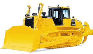
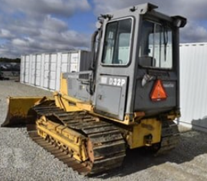
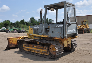
Komatsu Forklift Truck FD30HC-16
Need answers fast?
Explore the manual using AI.
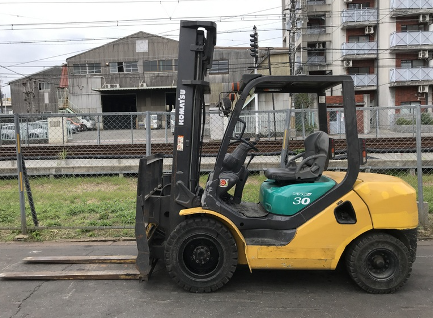
The Komatsu Forklift Truck FD30HC-16 is a robust and reliable industrial asset designed for heavy lifting and material handling. Known for its durability and efficiency, this forklift model excels in various warehouse and construction applications, ensuring optimal performance and safety in demanding environments.
Turn manuals into instant answers
with your AI-powered assistantTurn manuals into instant answers
with your AI-powered assistant
Manual for Komatsu Forklift Truck FD30HC-16
Complete asset maintenance, one click away
Get instant access to all the maintenance information you need. Empower technicians to perform preventive maintenance with asset packages, ready to use right out of the box.

Documents & Manuals
Find all the essential guides in one place.
 Tensioning Guide
- Belt-diagram
- C-120 pulleys
+ 13 more

Work Order Templates
Pre-built workflows to keep your asset running smoothly.
- Daily Electrical System Inspection
- Replace Roller and Pulley
- Install Engine B-120
+ 29 more

Procedures
Integrate maintenance plans directly into your work orders.
- Motion Industries
- Applied Industrial Technologies
- Electrical Brothers
+ 5 more

Parts
Access the parts list for your equipment in MaintainX.
- Drive Motor
- B2 Rollers
- Tensioning System
+ 40 more
Komatsu Forklift Truck FD30HC-16
Create an account to install this asset package.
Maintenance Plans for Komatsu Forklift Truck Model FD30HC-16
Integrate maintenance plans directly into your work orders in MaintainX.
Clutch And Brake Pedal Adjustment
1. PROCEDURE FOR ADJUSTMENT OF CLUTCH AND BRAKE PEDAL (CLUTCH MODEL)
1) Brake pedal stroke
If the brake pedal stroke is more than the standard, check the brake shoe for wear.
2) Adjust the height of the brake pedal with the stopper bolt (1) to make it approximately 137 mm from the floor plate.
3) Adjust the height of the clutch pedal with the stopper bolt (2) to make it approximately 153 mm from the floor plate.
2. PROCEDURE FOR ADJUSTMENT OF STOP LAMP SWITCH
Set the measurement "C" at the range of 0.5 mm through 1.5 mm after adjustment of the brake pedal height.;

Strainer Maintenance
Warning: This procedure requires trained personnel with PPE!
Drain plug removed and oil drained
Mounting bolt removed and strainer taken out for cleaning
Strainer cleaned with flushing oil
Strainer dried with compressed air from inside to outside
Any damage or clogs found on the strainer?
Action taken on the strainer
Amount of oil refilled
Oil level checked after refilling
Accelerator Pedal Adjustment
K15/K21/K25 ENGINE MODEL
PROCEDURE FOR ADJUSTMENT OF ACCELERATOR PEDAL
1. Set the stopper bolt (1) temporarily with the height of 65 mm.
2. After assembling the cable, adjust the outer casing mount of the cable to allow the pedal play of 2 to 3 mm.
3. Adjust the height of stopper bolt (1) again to allow the engine full throttle when flooring the accelerator pedal.
4D92E/4D94LE/4D98E ENGINE MODEL
PROCEDURE FOR ADJUSTMENT OF ACCELERATOR PEDAL
1. Set the stopper bolt (1) temporarily with the height of 65 mm.
2. After assembling the cable, adjust the outer casing mount of the cable to allow the pedal play between 2 to 3 mm.
Clutch Disc Replacement
Open the clutch case cover
Fix the pressure plate with the pressure plate mounting bolt
Slide the snap ring (1) and remove the pin (2)
Push the shaft toward the transmission
Remove the pressure plate mounting bolt (3) and slide the pressure plate
Remove the clutch disc
Be careful not to damage the spring when sliding the pressure plate
Sign off on the clutch disc replacement
Wheel Brake Adjustment
PROCEDURE FOR ADJUSTMENT OF BRAKE SHOE CLEARANCE
Release the parking brake while floating the wheels up above the ground.
Remove the rubber cap.
Turn the gear (1) in the direction (A) or toward the brake shoes repeatedly with a screwdriver until the brake shoes should touch the brake drum. Turning of every notch makes sound of clicks.
IMPORTANT: Turn the wheels by hands to feel braking a little bit.
Prepare two screwdrivers. The first screwdriver should be used for mildly pushing the lever (2) and have it miss each gear notch. Be careful not to push strongly. The second one should be used for turning the gear (1) toward the direction (B) counting by twenty-one (21) notches while the fist one is still on duty. It counts 30 notches for one turning of the gear.
IMPORTANT: Since no clicks are made available here, count the number of notches watching through the hole of the rubber cap (3) for carrying out the adjustment.
Install the rubber cap (3).
Turn the wheels by hands and check to make sure that there is no brake dragging.
Parts for Komatsu Forklift Truck FD30HC-16
Access the parts list for your equipment in MaintainX.
Fixing Bolt M10 1.5 × 65
01010-51065
Fixing Bolt M10 1.5 × 65
01010-51065
Fixing Bolt M10 1.5 × 65
01010-51065
Unlock efficiency
with MaintainX CoPilot
MaintainX CoPilot is your expert colleague, on call 24/7, helping your team find the answers they need to keep equipment running.
Reduce Unplanned Downtime
Ensure your team follows consistent procedures to minimize equipment failures and costly delays.
Maximize Asset Availability
Keep your assets running longer and more reliably, with standardized maintenance workflows from OEM manuals.
Lower Maintenance Costs
Turn any technician into an expert to streamline operations, maintain more assets, and reduce overall costs.
Thousands of companies manage their assets with MaintainX

'%3e%3cpath%20fill='url(%23b)'%20d='M66.008%2080.068c-5.084-.786-9.763-3.834-12.442-8.68a16.942%2016.942%200%200%201-1.87-5.18c1.096.19%202.203.476%203.298.87%206.525%202.333%2010.836%207.68%2011.014%2012.99ZM51.47%2061.576c.488-5.524%203.62-10.716%208.847-13.597a17.132%2017.132%200%200%201%2011.335-1.882c-.798%208.145-7.43%2014.848-16.038%2015.599-1.417.119-2.799.07-4.144-.12Zm28.564-11.478a17.513%2017.513%200%200%201%203.727%204.62c4.608%208.335%201.584%2018.813-6.75%2023.409a16.988%2016.988%200%200%201-4.359%201.679%2019.624%2019.624%200%200%201-3.977-12.776c.346-7.561%204.942-13.931%2011.36-16.932Z'/%3e%3cpath%20fill='%23110F0D'%20fill-rule='evenodd'%20d='M142.831%2048.324h4.977V77.03h-4.977V48.324Zm27.278%2013.002c.322%201.048.453%202.263.453%203.62v12.073h-4.787V66.208c0-.75-.047-1.572-.154-2.143-.453-2.382-1.822-3.572-4.215-3.572-2.31%200-3.882%201.274-4.43%203.476-.143.596-.226%201.405-.226%202.25v10.8h-4.787V56.623h4.477v2.989c1.536-2.5%203.906-3.43%206.371-3.43%203.488%200%206.263%201.68%207.298%205.144Zm24.636%207.323c0%203.882-2.358%206.525-5.763%207.727-1.298.453-2.632.643-4.62.643h-10.169V48.324h9.085c1.691%200%203.156.143%204.049.38%203.465.93%205.727%203.68%205.727%207.335%200%202.441-.81%204.156-2.762%205.644%202.905%201.417%204.453%203.727%204.453%206.966Zm-15.634-8.656h4.584c1.024%200%201.917-.143%202.536-.417%201.215-.548%201.905-1.608%201.905-3.167%200-1.548-.643-2.572-1.845-3.132-.691-.31-1.762-.452-2.763-.452h-4.417v7.168Zm10.716%208.465c0-1.536-.893-3.37-3.227-3.893-.428-.095-1.036-.143-1.571-.143h-5.918v8.085h5.501c.56%200%201.429-.048%201.953-.167%201.94-.453%203.262-1.846%203.262-3.882Zm47.747-11.847-8.097%2020.408h-4.429l-8.109-20.408h5.191l5.192%2014.574%205.108-14.574h5.144Zm-20.218%2010.002c0%20.69-.036%201.262-.155%201.94h-15.943c.631%202.87%202.714%204.728%205.882%204.728%202.131%200%203.607-.882%204.703-2.525h4.87c-1.762%204.144-5.204%206.692-9.657%206.692-6.084%200-10.537-4.858-10.537-10.49%200-6.108%204.524-10.776%2010.335-10.776%206.239%200%2010.442%204.954%2010.502%2010.43Zm-4.763-1.405c-.333-2.846-2.643-4.858-5.691-4.858-2.894%200-5.287%201.929-5.621%204.858h11.312Zm-72.667%203.44c0%204.787-3.287%208.371-9.419%208.371H119.363V64.66c-1.917.274-3.87.69-5.811%201.238l4.537%2011.121h-5.418l-3.596-9.585c-5.144%202.084-10.085%205.216-14.217%209.585h-4.786L101.8%2048.312h4.56l5.68%2013.883a44.112%2044.112%200%200%201%207.323-1.774V48.312h9.084c1.703%200%203.156.143%204.061.393%203.453.929%205.727%203.667%205.727%207.323%200%201.917-.738%204.179-2.81%205.691%203.06%201.56%204.501%204.025%204.501%206.93Zm-15.634-8.667a62.664%2062.664%200%200%201%202.06-.036c1.703.012%203.239.131%204.608.37%201.441-.549%202.357-1.727%202.357-3.537%200-1.941-.881-3.144-2.488-3.667-.548-.18-1.358-.286-2.322-.286h-4.215v7.156Zm-16.55%203.905-3.715-9.894-6.394%2016.502c2.833-2.595%206.263-4.858%2010.109-6.608Zm27.254%204.74c0-2.775-3.131-4.347-8.513-4.418-.715%200-1.441.011-2.191.047v8.252h5.918c2.548%200%204.786-1.37%204.786-3.882Z'%20clip-rule='evenodd'/%3e%3c/g%3e%3cdefs%3e%3clinearGradient%20id='b'%20x1='51.47'%20x2='85.916'%20y1='62.946'%20y2='62.946'%20gradientUnits='userSpaceOnUse'%3e%3cstop%20stop-color='%23CD9F28'/%3e%3cstop%20offset='1'%20stop-color='%23ECD80B'/%3e%3c/linearGradient%3e%3cclipPath%20id='a'%3e%3cpath%20fill='%23fff'%20d='M51.47%2045.728h186.104V80.14H51.47z'/%3e%3c/clipPath%3e%3c/defs%3e%3c/svg%3e)


More from Komatsu

Explore Other Assets


© 2026 MaintainX. All rights reserved.