


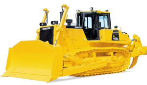
Komatsu Forklift Truck FD25NT-16
Need answers fast?
Explore the manual using AI.
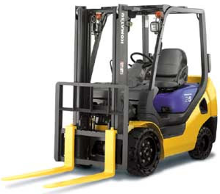
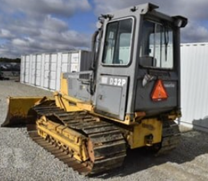
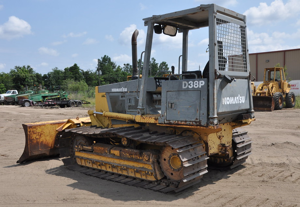
The Komatsu Forklift Truck FD25NT-16 is a robust and reliable industrial asset designed for heavy-duty lifting and material handling. Known for its durability and efficiency, this forklift model is ideal for various warehouse and construction applications, ensuring optimal performance in demanding environments.
Turn manuals into instant answers
with your AI-powered assistantTurn manuals into instant answers
with your AI-powered assistant
Manual for Komatsu Forklift Truck FD25NT-16
Complete asset maintenance, one click away
Get instant access to all the maintenance information you need. Empower technicians to perform preventive maintenance with asset packages, ready to use right out of the box.

Documents & Manuals
Find all the essential guides in one place.
 Tensioning Guide
- Belt-diagram
- C-120 pulleys
+ 13 more

Work Order Templates
Pre-built workflows to keep your asset running smoothly.
- Daily Electrical System Inspection
- Replace Roller and Pulley
- Install Engine B-120
+ 29 more

Procedures
Integrate maintenance plans directly into your work orders.
- Motion Industries
- Applied Industrial Technologies
- Electrical Brothers
+ 5 more

Parts
Access the parts list for your equipment in MaintainX.
- Drive Motor
- B2 Rollers
- Tensioning System
+ 40 more
Komatsu Forklift Truck FD25NT-16
Create an account to install this asset package.
Maintenance Plans for Komatsu Forklift Truck Model FD25NT-16
Integrate maintenance plans directly into your work orders in MaintainX.
Diesel Engine Adjustment
WHEN DISASSEMBLING AND ASSEMBLING
Match the injection pump with the A mark
Match the top mark B with the ATDC 5 degrees
Enter the plunger lift measurement
If the plunger lift is not in 1 mm, adjust the angle of the injection pump mounting
Sign off on the diesel engine adjustment

Accelerator Pedal Adjustment
K15/K21/K25 ENGINE MODEL
PROCEDURE FOR ADJUSTMENT OF ACCELERATOR PEDAL
1. Set the stopper bolt (1) temporarily with the height of 65 mm.
2. After assembling the cable, adjust the outer casing mount of the cable to allow the pedal play of 2 to 3 mm.
3. Adjust the height of stopper bolt (1) again to allow the engine full throttle when flooring the accelerator pedal.
4D92E/4D94LE/4D98E ENGINE MODEL
PROCEDURE FOR ADJUSTMENT OF ACCELERATOR PEDAL
1. Set the stopper bolt (1) temporarily with the height of 65 mm.
2. After assembling the cable, adjust the outer casing mount of the cable to allow the pedal play between 2 to 3 mm.
2 Yearly Forklift Truck Replacement
Warning: This replacement procedure requires trained personnel with PPE!
Select the parts replaced
Brake hose or tube replaced?
Reservior tank and tube replaced?
Power steering hose replaced?
Stop lamp switch (Oil pressure type) replaced?
Fuel hose replaced?
Rubber parts of power steering replaced?
Hose of load handing replaced?
Air Cleaner Element Cleaning
AIR CLEANER (1.0 – 1.75 TON)
WARNING
• Neither cleaning of the air cleaner nor replacement of the element is allowed while the engine is in motion.
• Always put the safety glasses on to protect your eyes when using the compressed air for cleaning the element upÅD
IMPORTANT
• If any grease or carbon is found stuck on the element, clean it up with a special cleaner according to the instruction for the air cleaner.
• In case of sever working conditions or environments, clean or replace the element earlier than regular maintenance.
1. Remove the element and blow the dry compressed air ( 0.69 MPa {7 kgf/cm2}) from inside to outside of the element for cleaning the whole element.
2. Put the cleaned element back to the air cleaner.
Air Cleaner Element Replacement
AIR CLEANER (1.0 – 1.75 TON)
1. Remove the element from the air cleaner.
2. Cover the air connector with clean cloth or tape.
3. Clean the interior of the air cleaner and remove the cover from the air cleaner.
4. Put a new element into the air cleaner.
AIR CLEANER (2 TON)
1. Remove the element from the air cleaner.
2. Remove the inner element.
3. Cover the air connector with clean cloth or tape.
Parts for Komatsu Forklift Truck FD25NT-16
Access the parts list for your equipment in MaintainX.
Fixing Bolt M10 1.5 × 65
01010-51065
Fixing Bolt M10 1.5 × 65
01010-51065
Fixing Bolt M10 1.5 × 65
01010-51065
Unlock efficiency
with MaintainX CoPilot
MaintainX CoPilot is your expert colleague, on call 24/7, helping your team find the answers they need to keep equipment running.
Reduce Unplanned Downtime
Ensure your team follows consistent procedures to minimize equipment failures and costly delays.
Maximize Asset Availability
Keep your assets running longer and more reliably, with standardized maintenance workflows from OEM manuals.
Lower Maintenance Costs
Turn any technician into an expert to streamline operations, maintain more assets, and reduce overall costs.
Thousands of companies manage their assets with MaintainX

'%3e%3cpath%20fill='url(%23b)'%20d='M66.008%2080.068c-5.084-.786-9.763-3.834-12.442-8.68a16.942%2016.942%200%200%201-1.87-5.18c1.096.19%202.203.476%203.298.87%206.525%202.333%2010.836%207.68%2011.014%2012.99ZM51.47%2061.576c.488-5.524%203.62-10.716%208.847-13.597a17.132%2017.132%200%200%201%2011.335-1.882c-.798%208.145-7.43%2014.848-16.038%2015.599-1.417.119-2.799.07-4.144-.12Zm28.564-11.478a17.513%2017.513%200%200%201%203.727%204.62c4.608%208.335%201.584%2018.813-6.75%2023.409a16.988%2016.988%200%200%201-4.359%201.679%2019.624%2019.624%200%200%201-3.977-12.776c.346-7.561%204.942-13.931%2011.36-16.932Z'/%3e%3cpath%20fill='%23110F0D'%20fill-rule='evenodd'%20d='M142.831%2048.324h4.977V77.03h-4.977V48.324Zm27.278%2013.002c.322%201.048.453%202.263.453%203.62v12.073h-4.787V66.208c0-.75-.047-1.572-.154-2.143-.453-2.382-1.822-3.572-4.215-3.572-2.31%200-3.882%201.274-4.43%203.476-.143.596-.226%201.405-.226%202.25v10.8h-4.787V56.623h4.477v2.989c1.536-2.5%203.906-3.43%206.371-3.43%203.488%200%206.263%201.68%207.298%205.144Zm24.636%207.323c0%203.882-2.358%206.525-5.763%207.727-1.298.453-2.632.643-4.62.643h-10.169V48.324h9.085c1.691%200%203.156.143%204.049.38%203.465.93%205.727%203.68%205.727%207.335%200%202.441-.81%204.156-2.762%205.644%202.905%201.417%204.453%203.727%204.453%206.966Zm-15.634-8.656h4.584c1.024%200%201.917-.143%202.536-.417%201.215-.548%201.905-1.608%201.905-3.167%200-1.548-.643-2.572-1.845-3.132-.691-.31-1.762-.452-2.763-.452h-4.417v7.168Zm10.716%208.465c0-1.536-.893-3.37-3.227-3.893-.428-.095-1.036-.143-1.571-.143h-5.918v8.085h5.501c.56%200%201.429-.048%201.953-.167%201.94-.453%203.262-1.846%203.262-3.882Zm47.747-11.847-8.097%2020.408h-4.429l-8.109-20.408h5.191l5.192%2014.574%205.108-14.574h5.144Zm-20.218%2010.002c0%20.69-.036%201.262-.155%201.94h-15.943c.631%202.87%202.714%204.728%205.882%204.728%202.131%200%203.607-.882%204.703-2.525h4.87c-1.762%204.144-5.204%206.692-9.657%206.692-6.084%200-10.537-4.858-10.537-10.49%200-6.108%204.524-10.776%2010.335-10.776%206.239%200%2010.442%204.954%2010.502%2010.43Zm-4.763-1.405c-.333-2.846-2.643-4.858-5.691-4.858-2.894%200-5.287%201.929-5.621%204.858h11.312Zm-72.667%203.44c0%204.787-3.287%208.371-9.419%208.371H119.363V64.66c-1.917.274-3.87.69-5.811%201.238l4.537%2011.121h-5.418l-3.596-9.585c-5.144%202.084-10.085%205.216-14.217%209.585h-4.786L101.8%2048.312h4.56l5.68%2013.883a44.112%2044.112%200%200%201%207.323-1.774V48.312h9.084c1.703%200%203.156.143%204.061.393%203.453.929%205.727%203.667%205.727%207.323%200%201.917-.738%204.179-2.81%205.691%203.06%201.56%204.501%204.025%204.501%206.93Zm-15.634-8.667a62.664%2062.664%200%200%201%202.06-.036c1.703.012%203.239.131%204.608.37%201.441-.549%202.357-1.727%202.357-3.537%200-1.941-.881-3.144-2.488-3.667-.548-.18-1.358-.286-2.322-.286h-4.215v7.156Zm-16.55%203.905-3.715-9.894-6.394%2016.502c2.833-2.595%206.263-4.858%2010.109-6.608Zm27.254%204.74c0-2.775-3.131-4.347-8.513-4.418-.715%200-1.441.011-2.191.047v8.252h5.918c2.548%200%204.786-1.37%204.786-3.882Z'%20clip-rule='evenodd'/%3e%3c/g%3e%3cdefs%3e%3clinearGradient%20id='b'%20x1='51.47'%20x2='85.916'%20y1='62.946'%20y2='62.946'%20gradientUnits='userSpaceOnUse'%3e%3cstop%20stop-color='%23CD9F28'/%3e%3cstop%20offset='1'%20stop-color='%23ECD80B'/%3e%3c/linearGradient%3e%3cclipPath%20id='a'%3e%3cpath%20fill='%23fff'%20d='M51.47%2045.728h186.104V80.14H51.47z'/%3e%3c/clipPath%3e%3c/defs%3e%3c/svg%3e)


More from Komatsu

Explore Other Assets


© 2026 MaintainX. All rights reserved.