


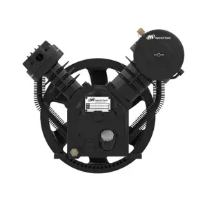
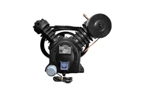
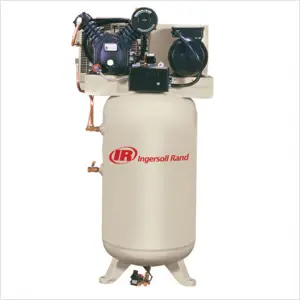
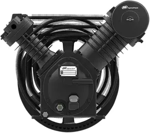
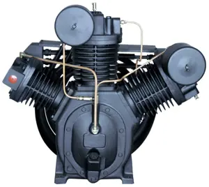
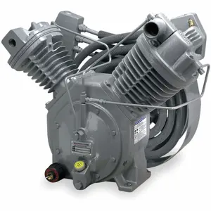
Ingersoll Rand Air Compressor SSR-ML55
Need answers fast?
Explore the manual using AI.
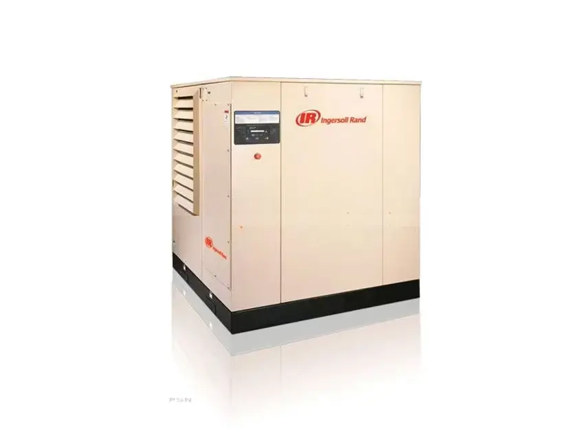
The Ingersoll Rand SSR-ML55 is a robust air compressor designed for industrial applications, offering reliable performance and efficiency. This model is ideal for various pneumatic tools and processes, ensuring optimal air delivery and minimal downtime in your operations.
Turn manuals into instant answers
with your AI-powered assistantTurn manuals into instant answers
with your AI-powered assistant
Manual for Ingersoll Rand Air Compressor SSR-ML55
Complete asset maintenance, one click away
Get instant access to all the maintenance information you need. Empower technicians to perform preventive maintenance with asset packages, ready to use right out of the box.

Documents & Manuals
Find all the essential guides in one place.
 Tensioning Guide
- Belt-diagram
- C-120 pulleys
+ 13 more

Work Order Templates
Pre-built workflows to keep your asset running smoothly.
- Daily Electrical System Inspection
- Replace Roller and Pulley
- Install Engine B-120
+ 29 more

Procedures
Integrate maintenance plans directly into your work orders.
- Motion Industries
- Applied Industrial Technologies
- Electrical Brothers
+ 5 more

Parts
Access the parts list for your equipment in MaintainX.
- Drive Motor
- B2 Rollers
- Tensioning System
+ 40 more
Ingersoll Rand Air Compressor SSR-ML55
Create an account to install this asset package.
Maintenance Plans for Ingersoll Rand Air Compressor Model SSR-ML55
Integrate maintenance plans directly into your work orders in MaintainX.
1 Yearly Air Filter Element Replacement
Time of change - when the panel mounted indicator lights up, or annually, when the coolant is changed. Indicator should be observed at full load.
Shut down the compressor.
Loosen wing nut on top of inlet filter housing. Lift cover up and away to expose element.
Carefully remove the old element to prevent dirt from entering the inlet valve. Discard old element.
Thoroughly clean the element housing and wipe all surfaces.
Install new element and inspect to insure that it has seated properly.
Install top of inlet filter housing.
Inspect the rubber seal on the retainer wing nut and replace seal if required.
Tighten wing nut.

Coolant-Lubricant Separator Element Replacement
CAUTION! Shut down the compressor, close the service air line isolation valve and open the main electrical disconnect switch. Confirm all air pressure is relieved from receiver.
Is the differential pressure across the element reaches three times the initial pressure drop or a maximum of 15 psi at full load?
Is there a drop to zero differential?
NOTE: A drop to zero differential also indicates a failing or by passing element that must be replaced.
Did you disconnect the scavenge tube at the airend?
Did you loosen the fitting that holds the scavenge tube into the tank and withdraw the tube assembly?
Did you disconnect the piping from the receiver cover?
Did you use a suitable wrench and remove the bolts that hold the tank cover in position?
Did you remove the cover by lifting up and away?
Initial 150 Hours Coolant Filter Element Replacement
WARNING! Confirm all pressure is relieved from the compressor system and that the main electric disconnect switch is open and tagged to remain open.
Pressure relieved from the compressor system?
Main electric disconnect switch is open and tagged to remain open?
Place a suitable container under the filter housing drain valve which is located near the bottom of the housing.
Container placed under the filter housing drain valve?
Remove the bolt at the bottom of the housing. This will free the housing and element from the filter head. Remove the 'O' ring gasket.
Bolt and 'O' ring gasket removed?
Inspect the element and housing for foreign particles which have been trapped in the element and also for general overall condition - then discard the element and clean the housing.
Element and housing inspected and cleaned?
Water Carryover to Discharge Lines Check
Warning: This check requires trained personnel!
Condensate trap is draining condensate
If condensate trap is not draining, report the issue to the maintenance team and stop the procedure
Is the aftercooler lowering the discharge air temperature below the dew point?
Under atmospheric conditions of very low humidity, is there no water vapor condensed?
Is there no flow from the condensate trap?
Is an open funnel used in the drain line for easier visual inspection?
Sign off on the water carryover to discharge lines check
2000 Hourly Coolant Filter Element Replacement
WARNING! Confirm all pressure is relieved from the compressor system and that the main electric disconnect switch is open and tagged to remain open.
Pressure relieved from the compressor system?
Main electric disconnect switch is open and tagged to remain open?
Place a suitable container under the filter housing drain valve which is located near the bottom of the housing.
Remove the bolt at the bottom of the housing. This will free the housing and element from the filter head. Remove the 'O' ring gasket.
Bolt at the bottom of the housing removed?
'O' ring gasket removed?
Inspect the element and housing for foreign particles which have been trapped in the element and also for general overall condition - then discard the element and clean the housing.
Element and housing inspected for foreign particles?
Unlock efficiency
with MaintainX CoPilot
MaintainX CoPilot is your expert colleague, on call 24/7, helping your team find the answers they need to keep equipment running.
Reduce Unplanned Downtime
Ensure your team follows consistent procedures to minimize equipment failures and costly delays.
Maximize Asset Availability
Keep your assets running longer and more reliably, with standardized maintenance workflows from OEM manuals.
Lower Maintenance Costs
Turn any technician into an expert to streamline operations, maintain more assets, and reduce overall costs.
Thousands of companies manage their assets with MaintainX

'%3e%3cpath%20fill='url(%23b)'%20d='M66.008%2080.068c-5.084-.786-9.763-3.834-12.442-8.68a16.942%2016.942%200%200%201-1.87-5.18c1.096.19%202.203.476%203.298.87%206.525%202.333%2010.836%207.68%2011.014%2012.99ZM51.47%2061.576c.488-5.524%203.62-10.716%208.847-13.597a17.132%2017.132%200%200%201%2011.335-1.882c-.798%208.145-7.43%2014.848-16.038%2015.599-1.417.119-2.799.07-4.144-.12Zm28.564-11.478a17.513%2017.513%200%200%201%203.727%204.62c4.608%208.335%201.584%2018.813-6.75%2023.409a16.988%2016.988%200%200%201-4.359%201.679%2019.624%2019.624%200%200%201-3.977-12.776c.346-7.561%204.942-13.931%2011.36-16.932Z'/%3e%3cpath%20fill='%23110F0D'%20fill-rule='evenodd'%20d='M142.831%2048.324h4.977V77.03h-4.977V48.324Zm27.278%2013.002c.322%201.048.453%202.263.453%203.62v12.073h-4.787V66.208c0-.75-.047-1.572-.154-2.143-.453-2.382-1.822-3.572-4.215-3.572-2.31%200-3.882%201.274-4.43%203.476-.143.596-.226%201.405-.226%202.25v10.8h-4.787V56.623h4.477v2.989c1.536-2.5%203.906-3.43%206.371-3.43%203.488%200%206.263%201.68%207.298%205.144Zm24.636%207.323c0%203.882-2.358%206.525-5.763%207.727-1.298.453-2.632.643-4.62.643h-10.169V48.324h9.085c1.691%200%203.156.143%204.049.38%203.465.93%205.727%203.68%205.727%207.335%200%202.441-.81%204.156-2.762%205.644%202.905%201.417%204.453%203.727%204.453%206.966Zm-15.634-8.656h4.584c1.024%200%201.917-.143%202.536-.417%201.215-.548%201.905-1.608%201.905-3.167%200-1.548-.643-2.572-1.845-3.132-.691-.31-1.762-.452-2.763-.452h-4.417v7.168Zm10.716%208.465c0-1.536-.893-3.37-3.227-3.893-.428-.095-1.036-.143-1.571-.143h-5.918v8.085h5.501c.56%200%201.429-.048%201.953-.167%201.94-.453%203.262-1.846%203.262-3.882Zm47.747-11.847-8.097%2020.408h-4.429l-8.109-20.408h5.191l5.192%2014.574%205.108-14.574h5.144Zm-20.218%2010.002c0%20.69-.036%201.262-.155%201.94h-15.943c.631%202.87%202.714%204.728%205.882%204.728%202.131%200%203.607-.882%204.703-2.525h4.87c-1.762%204.144-5.204%206.692-9.657%206.692-6.084%200-10.537-4.858-10.537-10.49%200-6.108%204.524-10.776%2010.335-10.776%206.239%200%2010.442%204.954%2010.502%2010.43Zm-4.763-1.405c-.333-2.846-2.643-4.858-5.691-4.858-2.894%200-5.287%201.929-5.621%204.858h11.312Zm-72.667%203.44c0%204.787-3.287%208.371-9.419%208.371H119.363V64.66c-1.917.274-3.87.69-5.811%201.238l4.537%2011.121h-5.418l-3.596-9.585c-5.144%202.084-10.085%205.216-14.217%209.585h-4.786L101.8%2048.312h4.56l5.68%2013.883a44.112%2044.112%200%200%201%207.323-1.774V48.312h9.084c1.703%200%203.156.143%204.061.393%203.453.929%205.727%203.667%205.727%207.323%200%201.917-.738%204.179-2.81%205.691%203.06%201.56%204.501%204.025%204.501%206.93Zm-15.634-8.667a62.664%2062.664%200%200%201%202.06-.036c1.703.012%203.239.131%204.608.37%201.441-.549%202.357-1.727%202.357-3.537%200-1.941-.881-3.144-2.488-3.667-.548-.18-1.358-.286-2.322-.286h-4.215v7.156Zm-16.55%203.905-3.715-9.894-6.394%2016.502c2.833-2.595%206.263-4.858%2010.109-6.608Zm27.254%204.74c0-2.775-3.131-4.347-8.513-4.418-.715%200-1.441.011-2.191.047v8.252h5.918c2.548%200%204.786-1.37%204.786-3.882Z'%20clip-rule='evenodd'/%3e%3c/g%3e%3cdefs%3e%3clinearGradient%20id='b'%20x1='51.47'%20x2='85.916'%20y1='62.946'%20y2='62.946'%20gradientUnits='userSpaceOnUse'%3e%3cstop%20stop-color='%23CD9F28'/%3e%3cstop%20offset='1'%20stop-color='%23ECD80B'/%3e%3c/linearGradient%3e%3cclipPath%20id='a'%3e%3cpath%20fill='%23fff'%20d='M51.47%2045.728h186.104V80.14H51.47z'/%3e%3c/clipPath%3e%3c/defs%3e%3c/svg%3e)


More from Ingersoll Rand


Explore Other Assets


© 2026 MaintainX. All rights reserved.