


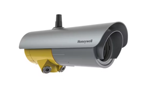
Honeywell Open Path Flammable Hydrocarbon Gas Detector Searchline Excel Edge Open Path GAS DETECTOR
Need answers fast?
Explore the manual using AI.

Turn manuals into instant answers
with your AI-powered assistantTurn manuals into instant answers
with your AI-powered assistant
Manual for Honeywell Open Path Flammable Hydrocarbon Gas Detector Searchline Excel Edge Open Path GAS DETECTOR
Complete asset maintenance, one click away
Get instant access to all the maintenance information you need. Empower technicians to perform preventive maintenance with asset packages, ready to use right out of the box.

Documents & Manuals
Find all the essential guides in one place.
 Tensioning Guide
- Belt-diagram
- C-120 pulleys
+ 13 more

Work Order Templates
Pre-built workflows to keep your asset running smoothly.
- Daily Electrical System Inspection
- Replace Roller and Pulley
- Install Engine B-120
+ 29 more

Procedures
Integrate maintenance plans directly into your work orders.
- Motion Industries
- Applied Industrial Technologies
- Electrical Brothers
+ 5 more

Parts
Access the parts list for your equipment in MaintainX.
- Drive Motor
- B2 Rollers
- Tensioning System
+ 40 more
Honeywell Open Path Flammable Hydrocarbon Gas Detector Searchline Excel Edge Open Path GAS DETECTOR
Create an account to install this asset package.
Maintenance Plans for Honeywell Open Path Flammable Hydrocarbon Gas Detector Model Searchline Excel Edge Open Path GAS DETECTOR
Integrate maintenance plans directly into your work orders in MaintainX.
Transmitter / Receiver Removal
Transmitter / Receiver Removal Procedure
Remove the bolt cover plate (Figure 13)
Hold the instrument body to prevent from tilting during disassembly and loosen the spigot vertical M10 bolt
Remove the instrument from its Universal Mounting Bracket
Sign off on the removal of the transmitter / receiver

Functional Test
Functional Testing using Functional Test Filters
In order to use the Functional Test Filters, access to the front of the receiver is required.
Note: Refer to the test sheet that was supplied with the receiver for the original filter and response measured by the factory. Wherever possible this should be used as a reference for all subsequent tests.
Note: An extender pole may be utilized for testing Searchline Excel at height.
9.3.1 Basic Functional Test
1. Ensure the area is gas free.
2. Ensure the receiver window is clean.
3. Slide the LOW TEST FILTER into the cowling at the front of receiver.
4. Receiver LED status indicator should flash red.
Calibration Check
CAUTION: Prerequisite for calibration check using the gassing test cell is installation of the Honeywell Fixed Platform App to the handheld device.
CAUTION: In some cases the use of the gassing test cell may distort Receiver alignment and trigger a misalignment warning indication during or shortly after the test. This warning indication is irrelevant to the test itself and can be ignored. The warning shall cease in 2 minutes after the gassing test cell is removed from the receiver unit.
The gassing test cell allows calibration to be checked using a user-specified gas concentration, as an alternative to the standard functional test filters.
The integrated LEL.m reading of the gas concentration in the test cell can be calculated using the following formula: Int(LEL.m)xl = Lcell * (Concgas / LELgas)
The test gas must be the same as the test gas used during the initial calibration of the Searchline Excel Plus & Searchline Excel Edge units and ideally the concentration should be between 2 and 5 LEL.m, never below 1 LEL.m.
Note: Cross-calibration is not recommended. Typical values for cross-sensitivity are not sufficiently precise to enable valid calibration checks using the gassing test cell.
Response tests can easily be performed with the functional test filters as described in Chapter 9.3.
WARNING: Take necessary precaution to ensure safety when dealing with high concentration gasses.
The gassing test cell supplied by Honeywell Analytics (Part No: 2017B0185) is 170 mm (6.7 in) long with gas path 138.8 mm (5.46 in) long and the following table outlines the response expected when using this gassing test cell:
Receiver Module Replacement
CAUTION: Front enclosures may be opened only for advised repair maintenance by an authorized and qualified person.
Note: This enables quick and easy repair via replacement of the electro-optical modules.
Unscrew the antenna cover from the top of the receiver and remove the sunshade.
Loosen the grub screw on the front cover.
Unscrew the front cover.
Follow the bayonet grooves and pull the module slightly out, then turn it counter-clockwise, and pull it out completely.
To re-assemble the receiver, perform the above procedure in reverse order.
Sign off on the receiver module replacement
Transmitter Module Replacement
CAUTION: Front enclosures may be opened only for advised repair maintenance by an authorized and qualified person.
Note: This enables quick and easy repair via replacement of the electro-optical modules.
Unscrew the antenna cover from the top of the transmitter and remove the sunshade.
Loosen the grub screw on the front cover.
Unscrew the front cover.
Follow the bayonet grooves and pull the module slightly out, then turn it clockwise, and pull it out completely.
To re-assemble the transmitter, perform the above procedure in reverse order.
Sign off on the transmitter module replacement
Unlock efficiency
with MaintainX CoPilot
MaintainX CoPilot is your expert colleague, on call 24/7, helping your team find the answers they need to keep equipment running.
Reduce Unplanned Downtime
Ensure your team follows consistent procedures to minimize equipment failures and costly delays.
Maximize Asset Availability
Keep your assets running longer and more reliably, with standardized maintenance workflows from OEM manuals.
Lower Maintenance Costs
Turn any technician into an expert to streamline operations, maintain more assets, and reduce overall costs.
Thousands of companies manage their assets with MaintainX

'%3e%3cpath%20fill='url(%23b)'%20d='M66.008%2080.068c-5.084-.786-9.763-3.834-12.442-8.68a16.942%2016.942%200%200%201-1.87-5.18c1.096.19%202.203.476%203.298.87%206.525%202.333%2010.836%207.68%2011.014%2012.99ZM51.47%2061.576c.488-5.524%203.62-10.716%208.847-13.597a17.132%2017.132%200%200%201%2011.335-1.882c-.798%208.145-7.43%2014.848-16.038%2015.599-1.417.119-2.799.07-4.144-.12Zm28.564-11.478a17.513%2017.513%200%200%201%203.727%204.62c4.608%208.335%201.584%2018.813-6.75%2023.409a16.988%2016.988%200%200%201-4.359%201.679%2019.624%2019.624%200%200%201-3.977-12.776c.346-7.561%204.942-13.931%2011.36-16.932Z'/%3e%3cpath%20fill='%23110F0D'%20fill-rule='evenodd'%20d='M142.831%2048.324h4.977V77.03h-4.977V48.324Zm27.278%2013.002c.322%201.048.453%202.263.453%203.62v12.073h-4.787V66.208c0-.75-.047-1.572-.154-2.143-.453-2.382-1.822-3.572-4.215-3.572-2.31%200-3.882%201.274-4.43%203.476-.143.596-.226%201.405-.226%202.25v10.8h-4.787V56.623h4.477v2.989c1.536-2.5%203.906-3.43%206.371-3.43%203.488%200%206.263%201.68%207.298%205.144Zm24.636%207.323c0%203.882-2.358%206.525-5.763%207.727-1.298.453-2.632.643-4.62.643h-10.169V48.324h9.085c1.691%200%203.156.143%204.049.38%203.465.93%205.727%203.68%205.727%207.335%200%202.441-.81%204.156-2.762%205.644%202.905%201.417%204.453%203.727%204.453%206.966Zm-15.634-8.656h4.584c1.024%200%201.917-.143%202.536-.417%201.215-.548%201.905-1.608%201.905-3.167%200-1.548-.643-2.572-1.845-3.132-.691-.31-1.762-.452-2.763-.452h-4.417v7.168Zm10.716%208.465c0-1.536-.893-3.37-3.227-3.893-.428-.095-1.036-.143-1.571-.143h-5.918v8.085h5.501c.56%200%201.429-.048%201.953-.167%201.94-.453%203.262-1.846%203.262-3.882Zm47.747-11.847-8.097%2020.408h-4.429l-8.109-20.408h5.191l5.192%2014.574%205.108-14.574h5.144Zm-20.218%2010.002c0%20.69-.036%201.262-.155%201.94h-15.943c.631%202.87%202.714%204.728%205.882%204.728%202.131%200%203.607-.882%204.703-2.525h4.87c-1.762%204.144-5.204%206.692-9.657%206.692-6.084%200-10.537-4.858-10.537-10.49%200-6.108%204.524-10.776%2010.335-10.776%206.239%200%2010.442%204.954%2010.502%2010.43Zm-4.763-1.405c-.333-2.846-2.643-4.858-5.691-4.858-2.894%200-5.287%201.929-5.621%204.858h11.312Zm-72.667%203.44c0%204.787-3.287%208.371-9.419%208.371H119.363V64.66c-1.917.274-3.87.69-5.811%201.238l4.537%2011.121h-5.418l-3.596-9.585c-5.144%202.084-10.085%205.216-14.217%209.585h-4.786L101.8%2048.312h4.56l5.68%2013.883a44.112%2044.112%200%200%201%207.323-1.774V48.312h9.084c1.703%200%203.156.143%204.061.393%203.453.929%205.727%203.667%205.727%207.323%200%201.917-.738%204.179-2.81%205.691%203.06%201.56%204.501%204.025%204.501%206.93Zm-15.634-8.667a62.664%2062.664%200%200%201%202.06-.036c1.703.012%203.239.131%204.608.37%201.441-.549%202.357-1.727%202.357-3.537%200-1.941-.881-3.144-2.488-3.667-.548-.18-1.358-.286-2.322-.286h-4.215v7.156Zm-16.55%203.905-3.715-9.894-6.394%2016.502c2.833-2.595%206.263-4.858%2010.109-6.608Zm27.254%204.74c0-2.775-3.131-4.347-8.513-4.418-.715%200-1.441.011-2.191.047v8.252h5.918c2.548%200%204.786-1.37%204.786-3.882Z'%20clip-rule='evenodd'/%3e%3c/g%3e%3cdefs%3e%3clinearGradient%20id='b'%20x1='51.47'%20x2='85.916'%20y1='62.946'%20y2='62.946'%20gradientUnits='userSpaceOnUse'%3e%3cstop%20stop-color='%23CD9F28'/%3e%3cstop%20offset='1'%20stop-color='%23ECD80B'/%3e%3c/linearGradient%3e%3cclipPath%20id='a'%3e%3cpath%20fill='%23fff'%20d='M51.47%2045.728h186.104V80.14H51.47z'/%3e%3c/clipPath%3e%3c/defs%3e%3c/svg%3e)


More from Honeywell


Explore Other Assets


© 2026 MaintainX. All rights reserved.