


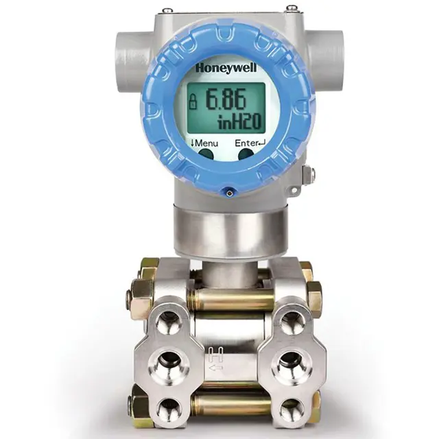
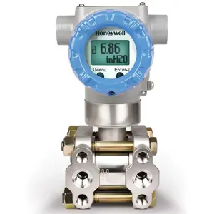
Honeywell Pressure Transmitter STG740
Need answers fast?
Explore the manual using AI.
Turn manuals into instant answers
with your AI-powered assistantTurn manuals into instant answers
with your AI-powered assistant
Manual for Honeywell Pressure Transmitter STG740
Complete asset maintenance, one click away
Get instant access to all the maintenance information you need. Empower technicians to perform preventive maintenance with asset packages, ready to use right out of the box.

Documents & Manuals
Find all the essential guides in one place.
 Tensioning Guide
- Belt-diagram
- C-120 pulleys
+ 13 more

Work Order Templates
Pre-built workflows to keep your asset running smoothly.
- Daily Electrical System Inspection
- Replace Roller and Pulley
- Install Engine B-120
+ 29 more

Procedures
Integrate maintenance plans directly into your work orders.
- Motion Industries
- Applied Industrial Technologies
- Electrical Brothers
+ 5 more

Parts
Access the parts list for your equipment in MaintainX.
- Drive Motor
- B2 Rollers
- Tensioning System
+ 40 more
Honeywell Pressure Transmitter STG740
Create an account to install this asset package.
Maintenance Plans for Honeywell Pressure Transmitter Model STG740
Integrate maintenance plans directly into your work orders in MaintainX.
Transmitter Calibration
Warning: Only trained personnel should perform this procedure.
Select the mode of operation
If operating in Analog mode, use Honeywell Smart Field Communicator (SFC) for calibration.
Refer to the Smart Field Communicator Operating Guide, Document # 34-ST-11-14 for calibration procedures.
If operating in HART/DE mode, refer to the ST 700 Series HART/DE Option User’s Manual, Document # 34-25-25-47.
Upload a photo of the calibrated transmitter
Sign off on the transmitter calibration

Communication Mode Replacement
Turn OFF Transmitter power
Loosen the end cap lock, and unscrew the end cap from the electronics side of the Transmitter housing
If equipped with a Display module, carefully depress the two tabs on the sides of the Display Module, and pull it off
If necessary, unplug the interface connector from the Communication module
Loosen the two retaining screws, and carefully pull the Communication module from the Electronics compartment
Carefully align and connect the Sensor Ribbon Cable to the connector “J4” at the bottom of the Communication module
Carefully, insert the Communication module into the Electronics compartment. Ensure that the Sensor Ribbon Cable is not pinched
Tighten the two Communication module retaining screws
Refer to the SmartLine User's Manual to change the FAILSAFE, READ/WRITE, and SIM- OFF/SIM-ON (Fieldbus Only) configuration settings
Meter Body Replacement
Save or record device configuration data.
Turn off Transmitter power.
Remove the Transmitter from service, and move it to a clean area before disassembling it.
Loosen the End Cap Lock, and unscrew the End Cap from the electronics side of the Transmitter housing.
If a display is present, press the two snaps along the side, and remove it from the communication module assembly.
Loosen the two retaining screws, and remove the Communications Module assembly, and remove the Communication Module assembly from the electronics housing.
Disconnect the Sensor Cable from the Communications Board.
Use a 2mm hex wrench to completely loosen the set screw on the outside of the housing to permit rotating the meter body.
Carefully turn the complete meter body counterclockwise to unscrew it from the electronics housing.
Transmitter Preventive Maintenance
Warning: This maintenance check requires trained personnel with PPE!
Check piping for leaks
Clear piping of sediment or other foreign matter
Clean the Transmitter process heads, including the barrier diaphragms
Sign off on the Transmitter preventive maintenance
Barrier Diaphragms Inspection and Cleaning
Valves closed to isolate the Transmitter from the process
Vent in the process head opened to drain fluid from the Transmitter meter body
Transmitter removed from the process
Nuts loosened in sequence
Nuts removed from the bolts that hold the process head(s) to the meter body
Process heads and bolts removed
Gasket/ O-ring removed and interior of the process head cleaned using a soft bristle brush and an approved solvent
Barrier diaphragm inspected for signs of deterioration, corrosion, and distortion
Is the diaphragm distorted?
Parts for Honeywell Pressure Transmitter STG740
Access the parts list for your equipment in MaintainX.
Carbon Steel Head (Zinc Plated) Without Side Vent/Drain, PTFE Gasket
51452864-010
Carbon Steel Head (Zinc Plated) With Side Vent/Drain, PTFE Gasket
51452864-012
Stainless Steel Head Without Side Vent/Drain, PTFE Gasket
51452864-020
Stainless Steel Head With Side Vent/Drain, PTFE Gasket
51452864-022
Hastelloy C Head Without Side Vent/Drain, PTFE Gasket
51452864-030
Unlock efficiency
with MaintainX CoPilot
MaintainX CoPilot is your expert colleague, on call 24/7, helping your team find the answers they need to keep equipment running.
Reduce Unplanned Downtime
Ensure your team follows consistent procedures to minimize equipment failures and costly delays.
Maximize Asset Availability
Keep your assets running longer and more reliably, with standardized maintenance workflows from OEM manuals.
Lower Maintenance Costs
Turn any technician into an expert to streamline operations, maintain more assets, and reduce overall costs.
Thousands of companies manage their assets with MaintainX

'%3e%3cpath%20fill='url(%23b)'%20d='M66.008%2080.068c-5.084-.786-9.763-3.834-12.442-8.68a16.942%2016.942%200%200%201-1.87-5.18c1.096.19%202.203.476%203.298.87%206.525%202.333%2010.836%207.68%2011.014%2012.99ZM51.47%2061.576c.488-5.524%203.62-10.716%208.847-13.597a17.132%2017.132%200%200%201%2011.335-1.882c-.798%208.145-7.43%2014.848-16.038%2015.599-1.417.119-2.799.07-4.144-.12Zm28.564-11.478a17.513%2017.513%200%200%201%203.727%204.62c4.608%208.335%201.584%2018.813-6.75%2023.409a16.988%2016.988%200%200%201-4.359%201.679%2019.624%2019.624%200%200%201-3.977-12.776c.346-7.561%204.942-13.931%2011.36-16.932Z'/%3e%3cpath%20fill='%23110F0D'%20fill-rule='evenodd'%20d='M142.831%2048.324h4.977V77.03h-4.977V48.324Zm27.278%2013.002c.322%201.048.453%202.263.453%203.62v12.073h-4.787V66.208c0-.75-.047-1.572-.154-2.143-.453-2.382-1.822-3.572-4.215-3.572-2.31%200-3.882%201.274-4.43%203.476-.143.596-.226%201.405-.226%202.25v10.8h-4.787V56.623h4.477v2.989c1.536-2.5%203.906-3.43%206.371-3.43%203.488%200%206.263%201.68%207.298%205.144Zm24.636%207.323c0%203.882-2.358%206.525-5.763%207.727-1.298.453-2.632.643-4.62.643h-10.169V48.324h9.085c1.691%200%203.156.143%204.049.38%203.465.93%205.727%203.68%205.727%207.335%200%202.441-.81%204.156-2.762%205.644%202.905%201.417%204.453%203.727%204.453%206.966Zm-15.634-8.656h4.584c1.024%200%201.917-.143%202.536-.417%201.215-.548%201.905-1.608%201.905-3.167%200-1.548-.643-2.572-1.845-3.132-.691-.31-1.762-.452-2.763-.452h-4.417v7.168Zm10.716%208.465c0-1.536-.893-3.37-3.227-3.893-.428-.095-1.036-.143-1.571-.143h-5.918v8.085h5.501c.56%200%201.429-.048%201.953-.167%201.94-.453%203.262-1.846%203.262-3.882Zm47.747-11.847-8.097%2020.408h-4.429l-8.109-20.408h5.191l5.192%2014.574%205.108-14.574h5.144Zm-20.218%2010.002c0%20.69-.036%201.262-.155%201.94h-15.943c.631%202.87%202.714%204.728%205.882%204.728%202.131%200%203.607-.882%204.703-2.525h4.87c-1.762%204.144-5.204%206.692-9.657%206.692-6.084%200-10.537-4.858-10.537-10.49%200-6.108%204.524-10.776%2010.335-10.776%206.239%200%2010.442%204.954%2010.502%2010.43Zm-4.763-1.405c-.333-2.846-2.643-4.858-5.691-4.858-2.894%200-5.287%201.929-5.621%204.858h11.312Zm-72.667%203.44c0%204.787-3.287%208.371-9.419%208.371H119.363V64.66c-1.917.274-3.87.69-5.811%201.238l4.537%2011.121h-5.418l-3.596-9.585c-5.144%202.084-10.085%205.216-14.217%209.585h-4.786L101.8%2048.312h4.56l5.68%2013.883a44.112%2044.112%200%200%201%207.323-1.774V48.312h9.084c1.703%200%203.156.143%204.061.393%203.453.929%205.727%203.667%205.727%207.323%200%201.917-.738%204.179-2.81%205.691%203.06%201.56%204.501%204.025%204.501%206.93Zm-15.634-8.667a62.664%2062.664%200%200%201%202.06-.036c1.703.012%203.239.131%204.608.37%201.441-.549%202.357-1.727%202.357-3.537%200-1.941-.881-3.144-2.488-3.667-.548-.18-1.358-.286-2.322-.286h-4.215v7.156Zm-16.55%203.905-3.715-9.894-6.394%2016.502c2.833-2.595%206.263-4.858%2010.109-6.608Zm27.254%204.74c0-2.775-3.131-4.347-8.513-4.418-.715%200-1.441.011-2.191.047v8.252h5.918c2.548%200%204.786-1.37%204.786-3.882Z'%20clip-rule='evenodd'/%3e%3c/g%3e%3cdefs%3e%3clinearGradient%20id='b'%20x1='51.47'%20x2='85.916'%20y1='62.946'%20y2='62.946'%20gradientUnits='userSpaceOnUse'%3e%3cstop%20stop-color='%23CD9F28'/%3e%3cstop%20offset='1'%20stop-color='%23ECD80B'/%3e%3c/linearGradient%3e%3cclipPath%20id='a'%3e%3cpath%20fill='%23fff'%20d='M51.47%2045.728h186.104V80.14H51.47z'/%3e%3c/clipPath%3e%3c/defs%3e%3c/svg%3e)


More from Honeywell


Explore Other Assets


© 2026 MaintainX. All rights reserved.