


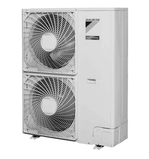
Daikin Outdoor Heat Pump RZQ160KV4A
Need answers fast?
Explore the manual using AI.

Turn manuals into instant answers
with your AI-powered assistantTurn manuals into instant answers
with your AI-powered assistant
Manual for Daikin Outdoor Heat Pump RZQ160KV4A
Complete asset maintenance, one click away
Get instant access to all the maintenance information you need. Empower technicians to perform preventive maintenance with asset packages, ready to use right out of the box.

Documents & Manuals
Find all the essential guides in one place.
 Tensioning Guide
- Belt-diagram
- C-120 pulleys
+ 13 more

Work Order Templates
Pre-built workflows to keep your asset running smoothly.
- Daily Electrical System Inspection
- Replace Roller and Pulley
- Install Engine B-120
+ 29 more

Procedures
Integrate maintenance plans directly into your work orders.
- Motion Industries
- Applied Industrial Technologies
- Electrical Brothers
+ 5 more

Parts
Access the parts list for your equipment in MaintainX.
- Drive Motor
- B2 Rollers
- Tensioning System
+ 40 more
Daikin Outdoor Heat Pump RZQ160KV4A
Create an account to install this asset package.
Maintenance Plans for Daikin Outdoor Heat Pump Model RZQ160KV4A
Integrate maintenance plans directly into your work orders in MaintainX.
Propeller Fan and Fan Motor Removal
Warning: Be sure to wait for 10 minutes or more after turning off all power supplies before disassembling work.
Remove the front panel (2) accordance with the Procedure to remove Outside Panels.
1. Remove the propeller fan
1 Unscrew the 4 screws that fix the air discharge grille and disengage the 4 hooks at the top and bottom of the grille, and then remove this air discharge grille.
2 Unfasten the fan lock nut that fixes the propeller fan.
2. Remove the fan motor
Remove the front panel (1) accordance with the Procedure to remove Outside Panels.
1 Remove the connector (X206A, X207A) for fan motor from the PCB.
In order to disconnect the connector, do not pull the lead wire. Hold the connector part and then press the hooks.

Outside Panel Removal
Warning: Be sure to wait for 10 minutes or more after turning off all power supplies before disassembling work.
Suction grille removed
Front panel (1) removed
Top panel removed
Front panel (1) removed
Front piping cover removed
Side piping cover removed
Side rear panel removed
Sign off on the panel removal
Pressure Sensor / Electronic Expansion Valve Removal
Warning: Be sure to wait for 10 minutes or more after turning off all power supplies before disassembling work.
Remove the top panel and the front panel (2) accordance with the Procedure to remove Outside Panels.
Before removing the solenoid valve or the electronic expansion valve, be sure to recover the refrigerant.
Precaution for mounting the coil for the electronic expansion valve
Align the dimple of the electronic expansion valve and the stopper of the electronic expansion valve coil, and then press them in until you hear them click.
1. Remove the pressure sensor
1 Disconnect the pressure sensor connector (X17A).
2 Use 2 spanners to remove the pressure sensor.
2. Remove the solenoid valve
Thermistor Removal
Warning: Be sure to wait for 10 minutes or more after turning off all power supplies before disassembling work.
Remove the top panel and the front panel (2) and side panel accordance with the Procedure to remove Outside Panels.
Pull out the outdoor air thermistor to the front, and then slide this thermistor to the right to remove it.
Pinch the mounting spring that fixes the discharge pipe thermistor to pull out this thermistor.
Press the fixing section of the suction pipe thermistor to pull out this thermistor.
Pull the fixing bracket of the heat exchanger’s distribution pipe thermistor to the front, and then remove this thermistor.
Press the fixing section of the intermediate heat exchanger thermistor to pull out this thermistor.
The heat exchanger’s distribution pipe thermistor, intermediate heat exchanger thermistor, and liquid pipe thermistor are jointed together with a single connector. Consequently, these 3 thermistors should be replaced at the same time.
Press the fixing section of the liquid pipe thermistor to pull out this thermistor.
Switch Box Removal
Warning: Be sure to wait for 10 minutes or more after turning off all power supplies before disassembling work.
Front panel removed in accordance with the Procedure to remove Outside Panels
Top panel removed
If the top panel cannot be removed, it is possible to pull the switch box to the front without removing the top panel.
Upload a photo of the disconnected connectors
Precaution for mounting the pressure sensor: To prevent the lead wire from hanging over the PCB, hook the lead wire of 160 to 170 mm in length from the front end of the connector on the clamp.
Each connector on the PCB disconnected
2 faston terminals removed
3 screws that fix the reactor unscrewed and reactor removed
Unlock efficiency
with MaintainX CoPilot
MaintainX CoPilot is your expert colleague, on call 24/7, helping your team find the answers they need to keep equipment running.
Reduce Unplanned Downtime
Ensure your team follows consistent procedures to minimize equipment failures and costly delays.
Maximize Asset Availability
Keep your assets running longer and more reliably, with standardized maintenance workflows from OEM manuals.
Lower Maintenance Costs
Turn any technician into an expert to streamline operations, maintain more assets, and reduce overall costs.
Thousands of companies manage their assets with MaintainX

'%3e%3cpath%20fill='url(%23b)'%20d='M66.008%2080.068c-5.084-.786-9.763-3.834-12.442-8.68a16.942%2016.942%200%200%201-1.87-5.18c1.096.19%202.203.476%203.298.87%206.525%202.333%2010.836%207.68%2011.014%2012.99ZM51.47%2061.576c.488-5.524%203.62-10.716%208.847-13.597a17.132%2017.132%200%200%201%2011.335-1.882c-.798%208.145-7.43%2014.848-16.038%2015.599-1.417.119-2.799.07-4.144-.12Zm28.564-11.478a17.513%2017.513%200%200%201%203.727%204.62c4.608%208.335%201.584%2018.813-6.75%2023.409a16.988%2016.988%200%200%201-4.359%201.679%2019.624%2019.624%200%200%201-3.977-12.776c.346-7.561%204.942-13.931%2011.36-16.932Z'/%3e%3cpath%20fill='%23110F0D'%20fill-rule='evenodd'%20d='M142.831%2048.324h4.977V77.03h-4.977V48.324Zm27.278%2013.002c.322%201.048.453%202.263.453%203.62v12.073h-4.787V66.208c0-.75-.047-1.572-.154-2.143-.453-2.382-1.822-3.572-4.215-3.572-2.31%200-3.882%201.274-4.43%203.476-.143.596-.226%201.405-.226%202.25v10.8h-4.787V56.623h4.477v2.989c1.536-2.5%203.906-3.43%206.371-3.43%203.488%200%206.263%201.68%207.298%205.144Zm24.636%207.323c0%203.882-2.358%206.525-5.763%207.727-1.298.453-2.632.643-4.62.643h-10.169V48.324h9.085c1.691%200%203.156.143%204.049.38%203.465.93%205.727%203.68%205.727%207.335%200%202.441-.81%204.156-2.762%205.644%202.905%201.417%204.453%203.727%204.453%206.966Zm-15.634-8.656h4.584c1.024%200%201.917-.143%202.536-.417%201.215-.548%201.905-1.608%201.905-3.167%200-1.548-.643-2.572-1.845-3.132-.691-.31-1.762-.452-2.763-.452h-4.417v7.168Zm10.716%208.465c0-1.536-.893-3.37-3.227-3.893-.428-.095-1.036-.143-1.571-.143h-5.918v8.085h5.501c.56%200%201.429-.048%201.953-.167%201.94-.453%203.262-1.846%203.262-3.882Zm47.747-11.847-8.097%2020.408h-4.429l-8.109-20.408h5.191l5.192%2014.574%205.108-14.574h5.144Zm-20.218%2010.002c0%20.69-.036%201.262-.155%201.94h-15.943c.631%202.87%202.714%204.728%205.882%204.728%202.131%200%203.607-.882%204.703-2.525h4.87c-1.762%204.144-5.204%206.692-9.657%206.692-6.084%200-10.537-4.858-10.537-10.49%200-6.108%204.524-10.776%2010.335-10.776%206.239%200%2010.442%204.954%2010.502%2010.43Zm-4.763-1.405c-.333-2.846-2.643-4.858-5.691-4.858-2.894%200-5.287%201.929-5.621%204.858h11.312Zm-72.667%203.44c0%204.787-3.287%208.371-9.419%208.371H119.363V64.66c-1.917.274-3.87.69-5.811%201.238l4.537%2011.121h-5.418l-3.596-9.585c-5.144%202.084-10.085%205.216-14.217%209.585h-4.786L101.8%2048.312h4.56l5.68%2013.883a44.112%2044.112%200%200%201%207.323-1.774V48.312h9.084c1.703%200%203.156.143%204.061.393%203.453.929%205.727%203.667%205.727%207.323%200%201.917-.738%204.179-2.81%205.691%203.06%201.56%204.501%204.025%204.501%206.93Zm-15.634-8.667a62.664%2062.664%200%200%201%202.06-.036c1.703.012%203.239.131%204.608.37%201.441-.549%202.357-1.727%202.357-3.537%200-1.941-.881-3.144-2.488-3.667-.548-.18-1.358-.286-2.322-.286h-4.215v7.156Zm-16.55%203.905-3.715-9.894-6.394%2016.502c2.833-2.595%206.263-4.858%2010.109-6.608Zm27.254%204.74c0-2.775-3.131-4.347-8.513-4.418-.715%200-1.441.011-2.191.047v8.252h5.918c2.548%200%204.786-1.37%204.786-3.882Z'%20clip-rule='evenodd'/%3e%3c/g%3e%3cdefs%3e%3clinearGradient%20id='b'%20x1='51.47'%20x2='85.916'%20y1='62.946'%20y2='62.946'%20gradientUnits='userSpaceOnUse'%3e%3cstop%20stop-color='%23CD9F28'/%3e%3cstop%20offset='1'%20stop-color='%23ECD80B'/%3e%3c/linearGradient%3e%3cclipPath%20id='a'%3e%3cpath%20fill='%23fff'%20d='M51.47%2045.728h186.104V80.14H51.47z'/%3e%3c/clipPath%3e%3c/defs%3e%3c/svg%3e)


More from Daikin


Explore Other Assets


© 2026 MaintainX. All rights reserved.