


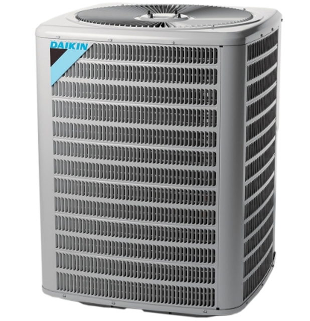
Daikin Condensing Unit DX13SA0483AD
Need answers fast?
Explore the manual using AI.
Turn manuals into instant answers
with your AI-powered assistantTurn manuals into instant answers
with your AI-powered assistant
Manual for Daikin Condensing Unit DX13SA0483AD
Complete asset maintenance, one click away
Get instant access to all the maintenance information you need. Empower technicians to perform preventive maintenance with asset packages, ready to use right out of the box.

Documents & Manuals
Find all the essential guides in one place.
 Tensioning Guide
- Belt-diagram
- C-120 pulleys
+ 13 more

Work Order Templates
Pre-built workflows to keep your asset running smoothly.
- Daily Electrical System Inspection
- Replace Roller and Pulley
- Install Engine B-120
+ 29 more

Procedures
Integrate maintenance plans directly into your work orders.
- Motion Industries
- Applied Industrial Technologies
- Electrical Brothers
+ 5 more

Parts
Access the parts list for your equipment in MaintainX.
- Drive Motor
- B2 Rollers
- Tensioning System
+ 40 more
Daikin Condensing Unit DX13SA0483AD
Create an account to install this asset package.
Maintenance Plans for Daikin Condensing Unit Model DX13SA0483AD
Integrate maintenance plans directly into your work orders in MaintainX.
Voltage Check
Warning: Line Voltage now present.
Outer case, control panel cover, etc., removed from unit being tested
Voltage across terminals L1 and L2 of the contactor or at the field connections for the air handler or heaters
No reading - indicates open wiring, open fuse(s) no power or etc., from unit to fused disconnect service. Repair as needed.
Ample voltage at line voltage connectors, unit energized
Voltage with the unit starting and operating
Locked Rotor Voltage
Locked rotor voltage within the voltage tabulation as shown
If the voltage falls below the minimum voltage, check the line wire size. Long runs of undersized wire can cause low voltage. If wire size is adequate, notify the local power company in regard to either low or high voltage.

Subcooling Check
Warning: This procedure requires trained personnel with PPE!
Attach a photo of the thermometer or thermocouple type temperature tester attached to the liquid line
Attach a photo of the high side pressure gauge installed on the high side service valve
Record the gauge pressure
Record the temperature of the line
Enter the design subcooling obtained from the technical information manual or specification sheet
Enter the hi-pressure reading from the 'Required Liquid Line Temperature' chart
Enter the temperature conversion from the liquid line pressure gauge reading
Enter the thermometer reading
Fan Relay Contact Check
WARNING: HIGH VOLTAGE! Disconnect ALL power before servicing or installing. Multiple power sources may be present. Failure to do so may cause property damage, personal injury or death.
Disconnect wire leads from terminals 2 and 4 of Fan Relay Cooling and 2 and 4, 5 and 6 of Fan Relay Heating.
Using an ohmmeter, test between 2 and 4 - should read open. Test between 5 and 6 - should read continuous.
WARNING: Line Voltage now present.
With power ON, energize the relays.
Using an ohmmeter, test between 2 and 4 - should read continuous . Test between 5 and 6 - should read open.
If not as above, replace the relay.
Sign off on the Fan Relay Contact Check
Leak Test
WARNING: To avoid the risk of fire or explosion, never use oxygen, high pressure air or flammable gases for leak testing of a refrigeration system.
WARNING: To avoid possible explosion, the line from the nitrogen cylinder must include a pressure regulator and a pressure relief valve. The pressure relief valve must be set to open at no more than 150 psig.
Pressure test the system using dry nitrogen and soapy water to locate leaks.
Charge the system to 10 psi using the appropriate refrigerant
Use nitrogen to finish charging the system to working pressure
Apply the detector to suspect areas
If leaks are found, repair them.
After repair, repeat the pressure test.
If no leaks exist, proceed to system evacuation.
Compressor Check
WARNING: Hermetic compressor electrical terminal venting can be dangerous.
If the compressor terminal PROTECTIVE COVER and gasket (if required) are not properly in place and secured, there is a remote possibility if a terminal vents, that the vaporous and liquid discharge can be ignited, spouting flames several feet, causing potentially severe or fatal injury to anyone in its path.
Ignition of the discharge can also occur at the venting terminal or inside the compressor, if there is sufficient contaminant air present in the system and an electrical arc occurs as the terminal vents.
Therefore, proper evacuation of a hermetic system is essential at the time of manufacture and during servicing.
To reduce the possibility of external ignition, all open flame, electrical power, and other heat sources should be extinguished or turned off prior to servicing a system.
Compressor terminal PROTECTIVE COVER and gasket properly in place and secured
Proper evacuation of a hermetic system performed
All open flame, electrical power, and other heat sources extinguished or turned off prior to servicing
Sign off on the compressor check
Unlock efficiency
with MaintainX CoPilot
MaintainX CoPilot is your expert colleague, on call 24/7, helping your team find the answers they need to keep equipment running.
Reduce Unplanned Downtime
Ensure your team follows consistent procedures to minimize equipment failures and costly delays.
Maximize Asset Availability
Keep your assets running longer and more reliably, with standardized maintenance workflows from OEM manuals.
Lower Maintenance Costs
Turn any technician into an expert to streamline operations, maintain more assets, and reduce overall costs.
Thousands of companies manage their assets with MaintainX

'%3e%3cpath%20fill='url(%23b)'%20d='M66.008%2080.068c-5.084-.786-9.763-3.834-12.442-8.68a16.942%2016.942%200%200%201-1.87-5.18c1.096.19%202.203.476%203.298.87%206.525%202.333%2010.836%207.68%2011.014%2012.99ZM51.47%2061.576c.488-5.524%203.62-10.716%208.847-13.597a17.132%2017.132%200%200%201%2011.335-1.882c-.798%208.145-7.43%2014.848-16.038%2015.599-1.417.119-2.799.07-4.144-.12Zm28.564-11.478a17.513%2017.513%200%200%201%203.727%204.62c4.608%208.335%201.584%2018.813-6.75%2023.409a16.988%2016.988%200%200%201-4.359%201.679%2019.624%2019.624%200%200%201-3.977-12.776c.346-7.561%204.942-13.931%2011.36-16.932Z'/%3e%3cpath%20fill='%23110F0D'%20fill-rule='evenodd'%20d='M142.831%2048.324h4.977V77.03h-4.977V48.324Zm27.278%2013.002c.322%201.048.453%202.263.453%203.62v12.073h-4.787V66.208c0-.75-.047-1.572-.154-2.143-.453-2.382-1.822-3.572-4.215-3.572-2.31%200-3.882%201.274-4.43%203.476-.143.596-.226%201.405-.226%202.25v10.8h-4.787V56.623h4.477v2.989c1.536-2.5%203.906-3.43%206.371-3.43%203.488%200%206.263%201.68%207.298%205.144Zm24.636%207.323c0%203.882-2.358%206.525-5.763%207.727-1.298.453-2.632.643-4.62.643h-10.169V48.324h9.085c1.691%200%203.156.143%204.049.38%203.465.93%205.727%203.68%205.727%207.335%200%202.441-.81%204.156-2.762%205.644%202.905%201.417%204.453%203.727%204.453%206.966Zm-15.634-8.656h4.584c1.024%200%201.917-.143%202.536-.417%201.215-.548%201.905-1.608%201.905-3.167%200-1.548-.643-2.572-1.845-3.132-.691-.31-1.762-.452-2.763-.452h-4.417v7.168Zm10.716%208.465c0-1.536-.893-3.37-3.227-3.893-.428-.095-1.036-.143-1.571-.143h-5.918v8.085h5.501c.56%200%201.429-.048%201.953-.167%201.94-.453%203.262-1.846%203.262-3.882Zm47.747-11.847-8.097%2020.408h-4.429l-8.109-20.408h5.191l5.192%2014.574%205.108-14.574h5.144Zm-20.218%2010.002c0%20.69-.036%201.262-.155%201.94h-15.943c.631%202.87%202.714%204.728%205.882%204.728%202.131%200%203.607-.882%204.703-2.525h4.87c-1.762%204.144-5.204%206.692-9.657%206.692-6.084%200-10.537-4.858-10.537-10.49%200-6.108%204.524-10.776%2010.335-10.776%206.239%200%2010.442%204.954%2010.502%2010.43Zm-4.763-1.405c-.333-2.846-2.643-4.858-5.691-4.858-2.894%200-5.287%201.929-5.621%204.858h11.312Zm-72.667%203.44c0%204.787-3.287%208.371-9.419%208.371H119.363V64.66c-1.917.274-3.87.69-5.811%201.238l4.537%2011.121h-5.418l-3.596-9.585c-5.144%202.084-10.085%205.216-14.217%209.585h-4.786L101.8%2048.312h4.56l5.68%2013.883a44.112%2044.112%200%200%201%207.323-1.774V48.312h9.084c1.703%200%203.156.143%204.061.393%203.453.929%205.727%203.667%205.727%207.323%200%201.917-.738%204.179-2.81%205.691%203.06%201.56%204.501%204.025%204.501%206.93Zm-15.634-8.667a62.664%2062.664%200%200%201%202.06-.036c1.703.012%203.239.131%204.608.37%201.441-.549%202.357-1.727%202.357-3.537%200-1.941-.881-3.144-2.488-3.667-.548-.18-1.358-.286-2.322-.286h-4.215v7.156Zm-16.55%203.905-3.715-9.894-6.394%2016.502c2.833-2.595%206.263-4.858%2010.109-6.608Zm27.254%204.74c0-2.775-3.131-4.347-8.513-4.418-.715%200-1.441.011-2.191.047v8.252h5.918c2.548%200%204.786-1.37%204.786-3.882Z'%20clip-rule='evenodd'/%3e%3c/g%3e%3cdefs%3e%3clinearGradient%20id='b'%20x1='51.47'%20x2='85.916'%20y1='62.946'%20y2='62.946'%20gradientUnits='userSpaceOnUse'%3e%3cstop%20stop-color='%23CD9F28'/%3e%3cstop%20offset='1'%20stop-color='%23ECD80B'/%3e%3c/linearGradient%3e%3cclipPath%20id='a'%3e%3cpath%20fill='%23fff'%20d='M51.47%2045.728h186.104V80.14H51.47z'/%3e%3c/clipPath%3e%3c/defs%3e%3c/svg%3e)


More from Daikin


Explore Other Assets


© 2026 MaintainX. All rights reserved.