


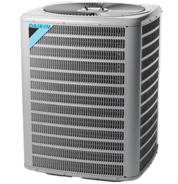
Daikin Condensing Unit DX13SA0421AE
Need answers fast?
Explore the manual using AI.
Turn manuals into instant answers
with your AI-powered assistantTurn manuals into instant answers
with your AI-powered assistant
Manual for Daikin Condensing Unit DX13SA0421AE
Complete asset maintenance, one click away
Get instant access to all the maintenance information you need. Empower technicians to perform preventive maintenance with asset packages, ready to use right out of the box.

Documents & Manuals
Find all the essential guides in one place.
 Tensioning Guide
- Belt-diagram
- C-120 pulleys
+ 13 more

Work Order Templates
Pre-built workflows to keep your asset running smoothly.
- Daily Electrical System Inspection
- Replace Roller and Pulley
- Install Engine B-120
+ 29 more

Procedures
Integrate maintenance plans directly into your work orders.
- Motion Industries
- Applied Industrial Technologies
- Electrical Brothers
+ 5 more

Parts
Access the parts list for your equipment in MaintainX.
- Drive Motor
- B2 Rollers
- Tensioning System
+ 40 more
Daikin Condensing Unit DX13SA0421AE
Create an account to install this asset package.
Maintenance Plans for Daikin Condensing Unit Model DX13SA0421AE
Integrate maintenance plans directly into your work orders in MaintainX.
Reversing Valve / Solenoid Check
Warning: This procedure requires trained personnel with PPE!
Reversing valve stuck in the mid-position?
Measure the suction line temperature through the reversing valve
Valve changes position when switching from COOLING to HEATING cycle?
Measure the voltage at the valve coil terminals during COOLING cycle
Voltage registered at the coil terminals?
Thermostat operational?
Continuity of the connecting wiring from the “O” terminal of the thermostat to the unit?
Sign off on the reversing valve / solenoid check

Heater Limit Control Check
WARNING: Disconnect ALL power before servicing.
Remove the wiring from the control terminals.
Using an ohmmeter, test for continuity across the normally closed contacts. No reading indicates the control is open.
Make sure the limits are cool before testing.
If found open, replace. Do not wire around.
Sign off on the heater limit control check
Ground Test
Warning: This procedure requires trained personnel with PPE!
Fuse, circuit breaker, ground fault protective device tripped?
If the protective device has tripped, an electrical problem exists and must be corrected.
Check the circuit protective device rating. It should coincide with the equipment nameplate.
Did the circuit breaker open again after resetting?
If it opens again, DO NOT continue to reset.
Disconnect all power to unit, ensuring all power legs are open.
DO NOT remove protective terminal cover. Disconnect the three leads going to the compressor terminals at the nearest point to the compressor.
Identify the leads
Subcooling Check
Warning: This procedure requires trained personnel with PPE!
Attach a photo of the thermometer or thermocouple type temperature tester attached to the liquid line as it leaves the condensing unit.
Attach a photo of the high side pressure gauge installed on the high side (liquid) service valve at the front of the unit.
Record the gauge pressure
Record the temperature of the line.
Enter the design subcooling obtained from the technical information manual or specification sheet for the model being serviced.
Enter the hi-pressure reading from the “Required Liquid Line Temperature” chart.
Enter the liquid line pressure gauge reading.
Enter the temperature from the Temperature - Pressure Chart.
Voltage Check
Remove outer case, control panel cover, etc., from unit being tested. WARNING: Line Voltage now present.
Measure the voltage across terminals L1 and L2 of the contactor for the condensing unit or at the field connections for the air handler or heaters.
Is there a reading?
If no reading, indicates open wiring, open fuse(s) no power or etc., from unit to fused disconnect service. Repair as needed.
With ample voltage at line voltage connectors, energize the unit.
Measure the voltage with the unit starting and operating, and determine the unit Locked Rotor Voltage.
Locked Rotor Voltage is the actual voltage available at the compressor during starting, locked rotor, or a stalled condition. Measured voltage should be above minimum listed in chart below.
To measure Locked Rotor Voltage attach a voltmeter to the run 'R' and common 'C' terminals of the compressor, or to the T1 and T2 terminals of the contactor. Start the unit and allow the compressor to run for several seconds, then shut down the unit. Immediately attempt to restart the unit while measuring the Locked Rotor Voltage.
Does the locked rotor voltage read within the voltage tabulation as shown?
Unlock efficiency
with MaintainX CoPilot
MaintainX CoPilot is your expert colleague, on call 24/7, helping your team find the answers they need to keep equipment running.
Reduce Unplanned Downtime
Ensure your team follows consistent procedures to minimize equipment failures and costly delays.
Maximize Asset Availability
Keep your assets running longer and more reliably, with standardized maintenance workflows from OEM manuals.
Lower Maintenance Costs
Turn any technician into an expert to streamline operations, maintain more assets, and reduce overall costs.
Thousands of companies manage their assets with MaintainX

'%3e%3cpath%20fill='url(%23b)'%20d='M66.008%2080.068c-5.084-.786-9.763-3.834-12.442-8.68a16.942%2016.942%200%200%201-1.87-5.18c1.096.19%202.203.476%203.298.87%206.525%202.333%2010.836%207.68%2011.014%2012.99ZM51.47%2061.576c.488-5.524%203.62-10.716%208.847-13.597a17.132%2017.132%200%200%201%2011.335-1.882c-.798%208.145-7.43%2014.848-16.038%2015.599-1.417.119-2.799.07-4.144-.12Zm28.564-11.478a17.513%2017.513%200%200%201%203.727%204.62c4.608%208.335%201.584%2018.813-6.75%2023.409a16.988%2016.988%200%200%201-4.359%201.679%2019.624%2019.624%200%200%201-3.977-12.776c.346-7.561%204.942-13.931%2011.36-16.932Z'/%3e%3cpath%20fill='%23110F0D'%20fill-rule='evenodd'%20d='M142.831%2048.324h4.977V77.03h-4.977V48.324Zm27.278%2013.002c.322%201.048.453%202.263.453%203.62v12.073h-4.787V66.208c0-.75-.047-1.572-.154-2.143-.453-2.382-1.822-3.572-4.215-3.572-2.31%200-3.882%201.274-4.43%203.476-.143.596-.226%201.405-.226%202.25v10.8h-4.787V56.623h4.477v2.989c1.536-2.5%203.906-3.43%206.371-3.43%203.488%200%206.263%201.68%207.298%205.144Zm24.636%207.323c0%203.882-2.358%206.525-5.763%207.727-1.298.453-2.632.643-4.62.643h-10.169V48.324h9.085c1.691%200%203.156.143%204.049.38%203.465.93%205.727%203.68%205.727%207.335%200%202.441-.81%204.156-2.762%205.644%202.905%201.417%204.453%203.727%204.453%206.966Zm-15.634-8.656h4.584c1.024%200%201.917-.143%202.536-.417%201.215-.548%201.905-1.608%201.905-3.167%200-1.548-.643-2.572-1.845-3.132-.691-.31-1.762-.452-2.763-.452h-4.417v7.168Zm10.716%208.465c0-1.536-.893-3.37-3.227-3.893-.428-.095-1.036-.143-1.571-.143h-5.918v8.085h5.501c.56%200%201.429-.048%201.953-.167%201.94-.453%203.262-1.846%203.262-3.882Zm47.747-11.847-8.097%2020.408h-4.429l-8.109-20.408h5.191l5.192%2014.574%205.108-14.574h5.144Zm-20.218%2010.002c0%20.69-.036%201.262-.155%201.94h-15.943c.631%202.87%202.714%204.728%205.882%204.728%202.131%200%203.607-.882%204.703-2.525h4.87c-1.762%204.144-5.204%206.692-9.657%206.692-6.084%200-10.537-4.858-10.537-10.49%200-6.108%204.524-10.776%2010.335-10.776%206.239%200%2010.442%204.954%2010.502%2010.43Zm-4.763-1.405c-.333-2.846-2.643-4.858-5.691-4.858-2.894%200-5.287%201.929-5.621%204.858h11.312Zm-72.667%203.44c0%204.787-3.287%208.371-9.419%208.371H119.363V64.66c-1.917.274-3.87.69-5.811%201.238l4.537%2011.121h-5.418l-3.596-9.585c-5.144%202.084-10.085%205.216-14.217%209.585h-4.786L101.8%2048.312h4.56l5.68%2013.883a44.112%2044.112%200%200%201%207.323-1.774V48.312h9.084c1.703%200%203.156.143%204.061.393%203.453.929%205.727%203.667%205.727%207.323%200%201.917-.738%204.179-2.81%205.691%203.06%201.56%204.501%204.025%204.501%206.93Zm-15.634-8.667a62.664%2062.664%200%200%201%202.06-.036c1.703.012%203.239.131%204.608.37%201.441-.549%202.357-1.727%202.357-3.537%200-1.941-.881-3.144-2.488-3.667-.548-.18-1.358-.286-2.322-.286h-4.215v7.156Zm-16.55%203.905-3.715-9.894-6.394%2016.502c2.833-2.595%206.263-4.858%2010.109-6.608Zm27.254%204.74c0-2.775-3.131-4.347-8.513-4.418-.715%200-1.441.011-2.191.047v8.252h5.918c2.548%200%204.786-1.37%204.786-3.882Z'%20clip-rule='evenodd'/%3e%3c/g%3e%3cdefs%3e%3clinearGradient%20id='b'%20x1='51.47'%20x2='85.916'%20y1='62.946'%20y2='62.946'%20gradientUnits='userSpaceOnUse'%3e%3cstop%20stop-color='%23CD9F28'/%3e%3cstop%20offset='1'%20stop-color='%23ECD80B'/%3e%3c/linearGradient%3e%3cclipPath%20id='a'%3e%3cpath%20fill='%23fff'%20d='M51.47%2045.728h186.104V80.14H51.47z'/%3e%3c/clipPath%3e%3c/defs%3e%3c/svg%3e)


More from Daikin


Explore Other Assets


© 2026 MaintainX. All rights reserved.