


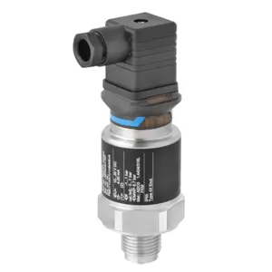
Daikin Air Conditioner RX30NMVJU
Need answers fast?
Explore the manual using AI.
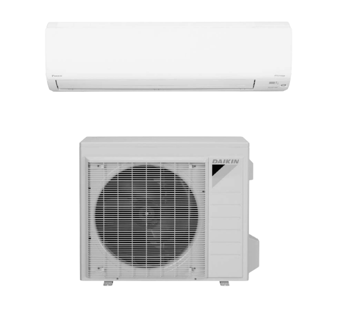
The Daikin Air Conditioner RX30NMVJU is a high-efficiency cooling solution designed for residential and commercial use. Known for its reliability and advanced technology, this model ensures optimal indoor comfort while minimizing energy consumption. Regular maintenance enhances its performance and longevity.
Turn manuals into instant answers
with your AI-powered assistantTurn manuals into instant answers
with your AI-powered assistant
Manual for Daikin Air Conditioner RX30NMVJU
Complete asset maintenance, one click away
Get instant access to all the maintenance information you need. Empower technicians to perform preventive maintenance with asset packages, ready to use right out of the box.

Documents & Manuals
Find all the essential guides in one place.
 Tensioning Guide
- Belt-diagram
- C-120 pulleys
+ 13 more

Work Order Templates
Pre-built workflows to keep your asset running smoothly.
- Daily Electrical System Inspection
- Replace Roller and Pulley
- Install Engine B-120
+ 29 more

Procedures
Integrate maintenance plans directly into your work orders.
- Motion Industries
- Applied Industrial Technologies
- Electrical Brothers
+ 5 more

Parts
Access the parts list for your equipment in MaintainX.
- Drive Motor
- B2 Rollers
- Tensioning System
+ 40 more
Daikin Air Conditioner RX30NMVJU
Create an account to install this asset package.
Maintenance Plans for Daikin Air Conditioner Model RX30NMVJU
Integrate maintenance plans directly into your work orders in MaintainX.
Capacitor Voltage Check
Warning: This procedure requires trained personnel with PPE!
Main circuit checked for short circuit?
Warning: Never touch any live parts during the procedure.
Voltage between FU2 and DC–
Is the voltage 50 V or less?
Note: The surface of the test points (DC–) may be covered with the coating.
Firm contact between the multimeter probes and the test points?
Sign off on the capacitor voltage check

Power Supply Waveforms Check
Warning: This check requires trained personnel with PPE!
Measure the power supply waveform between No. 1 and No. 2 on the terminal board
Is the power supply waveform a sine wave?
Is there waveform disturbance near the zero-cross?
Upload a photo of the waveform
Sign off on the power supply waveforms check
Main Circuit Short Check
Warning: Ensure the voltage between (+) and (-) of the diode bridge (DB1) is approximately 0 V before proceeding
Enter the voltage between (+) and (-) of the diode bridge (DB1)
Measure the resistance between the pins of the DB1 referring to the table below
Enter the resistance between the pins of the DB1
Is the resistance less than 1 kOhm?
If the resistance is less than 1 kOhm, a short circuit occurs on the main circuit
Sign off on the main circuit short check
Thermistor Resistance Check
Warning: Disconnect the connectors of the thermistors from the PCB before proceeding
Thermistors disconnected from the PCB
Resistance of each thermistor
Note: The room temperature thermistor is soldered on the PCB
Connector to the control PCB disconnected before measuring the resistance
When the connector of indoor heat exchanger thermistor is soldered on the PCB, remove the thermistor
Indoor heat exchanger thermistor removed
Resistance of the indoor heat exchanger thermistor
Sign off on the thermistor resistance check
Inverter Analyzer Check
Warning: This procedure requires trained personnel. Always ensure power is off before starting.
Is the power off?
If power is not off, turn it off and wait until the charged voltage of the built-in smoothing electrolytic capacitor drops to 10 VDC or below.
Is the charged voltage of the built-in smoothing electrolytic capacitor 10 VDC or below?
Install an inverter analyzer instead of a compressor.
Inverter analyzer installed correctly?
Activate power transistor test operation from the indoor unit.
Power transistor test operation activated?
Sign off on the inverter analyzer check
Parts for Daikin Air Conditioner RX30NMVJU
Access the parts list for your equipment in MaintainX.
Inverter Checker
1225477
Inverter Checker
1225477
Inverter Checker
1225477
Unlock efficiency
with MaintainX CoPilot
MaintainX CoPilot is your expert colleague, on call 24/7, helping your team find the answers they need to keep equipment running.
Reduce Unplanned Downtime
Ensure your team follows consistent procedures to minimize equipment failures and costly delays.
Maximize Asset Availability
Keep your assets running longer and more reliably, with standardized maintenance workflows from OEM manuals.
Lower Maintenance Costs
Turn any technician into an expert to streamline operations, maintain more assets, and reduce overall costs.
Thousands of companies manage their assets with MaintainX

'%3e%3cpath%20fill='url(%23b)'%20d='M66.008%2080.068c-5.084-.786-9.763-3.834-12.442-8.68a16.942%2016.942%200%200%201-1.87-5.18c1.096.19%202.203.476%203.298.87%206.525%202.333%2010.836%207.68%2011.014%2012.99ZM51.47%2061.576c.488-5.524%203.62-10.716%208.847-13.597a17.132%2017.132%200%200%201%2011.335-1.882c-.798%208.145-7.43%2014.848-16.038%2015.599-1.417.119-2.799.07-4.144-.12Zm28.564-11.478a17.513%2017.513%200%200%201%203.727%204.62c4.608%208.335%201.584%2018.813-6.75%2023.409a16.988%2016.988%200%200%201-4.359%201.679%2019.624%2019.624%200%200%201-3.977-12.776c.346-7.561%204.942-13.931%2011.36-16.932Z'/%3e%3cpath%20fill='%23110F0D'%20fill-rule='evenodd'%20d='M142.831%2048.324h4.977V77.03h-4.977V48.324Zm27.278%2013.002c.322%201.048.453%202.263.453%203.62v12.073h-4.787V66.208c0-.75-.047-1.572-.154-2.143-.453-2.382-1.822-3.572-4.215-3.572-2.31%200-3.882%201.274-4.43%203.476-.143.596-.226%201.405-.226%202.25v10.8h-4.787V56.623h4.477v2.989c1.536-2.5%203.906-3.43%206.371-3.43%203.488%200%206.263%201.68%207.298%205.144Zm24.636%207.323c0%203.882-2.358%206.525-5.763%207.727-1.298.453-2.632.643-4.62.643h-10.169V48.324h9.085c1.691%200%203.156.143%204.049.38%203.465.93%205.727%203.68%205.727%207.335%200%202.441-.81%204.156-2.762%205.644%202.905%201.417%204.453%203.727%204.453%206.966Zm-15.634-8.656h4.584c1.024%200%201.917-.143%202.536-.417%201.215-.548%201.905-1.608%201.905-3.167%200-1.548-.643-2.572-1.845-3.132-.691-.31-1.762-.452-2.763-.452h-4.417v7.168Zm10.716%208.465c0-1.536-.893-3.37-3.227-3.893-.428-.095-1.036-.143-1.571-.143h-5.918v8.085h5.501c.56%200%201.429-.048%201.953-.167%201.94-.453%203.262-1.846%203.262-3.882Zm47.747-11.847-8.097%2020.408h-4.429l-8.109-20.408h5.191l5.192%2014.574%205.108-14.574h5.144Zm-20.218%2010.002c0%20.69-.036%201.262-.155%201.94h-15.943c.631%202.87%202.714%204.728%205.882%204.728%202.131%200%203.607-.882%204.703-2.525h4.87c-1.762%204.144-5.204%206.692-9.657%206.692-6.084%200-10.537-4.858-10.537-10.49%200-6.108%204.524-10.776%2010.335-10.776%206.239%200%2010.442%204.954%2010.502%2010.43Zm-4.763-1.405c-.333-2.846-2.643-4.858-5.691-4.858-2.894%200-5.287%201.929-5.621%204.858h11.312Zm-72.667%203.44c0%204.787-3.287%208.371-9.419%208.371H119.363V64.66c-1.917.274-3.87.69-5.811%201.238l4.537%2011.121h-5.418l-3.596-9.585c-5.144%202.084-10.085%205.216-14.217%209.585h-4.786L101.8%2048.312h4.56l5.68%2013.883a44.112%2044.112%200%200%201%207.323-1.774V48.312h9.084c1.703%200%203.156.143%204.061.393%203.453.929%205.727%203.667%205.727%207.323%200%201.917-.738%204.179-2.81%205.691%203.06%201.56%204.501%204.025%204.501%206.93Zm-15.634-8.667a62.664%2062.664%200%200%201%202.06-.036c1.703.012%203.239.131%204.608.37%201.441-.549%202.357-1.727%202.357-3.537%200-1.941-.881-3.144-2.488-3.667-.548-.18-1.358-.286-2.322-.286h-4.215v7.156Zm-16.55%203.905-3.715-9.894-6.394%2016.502c2.833-2.595%206.263-4.858%2010.109-6.608Zm27.254%204.74c0-2.775-3.131-4.347-8.513-4.418-.715%200-1.441.011-2.191.047v8.252h5.918c2.548%200%204.786-1.37%204.786-3.882Z'%20clip-rule='evenodd'/%3e%3c/g%3e%3cdefs%3e%3clinearGradient%20id='b'%20x1='51.47'%20x2='85.916'%20y1='62.946'%20y2='62.946'%20gradientUnits='userSpaceOnUse'%3e%3cstop%20stop-color='%23CD9F28'/%3e%3cstop%20offset='1'%20stop-color='%23ECD80B'/%3e%3c/linearGradient%3e%3cclipPath%20id='a'%3e%3cpath%20fill='%23fff'%20d='M51.47%2045.728h186.104V80.14H51.47z'/%3e%3c/clipPath%3e%3c/defs%3e%3c/svg%3e)


More from Daikin


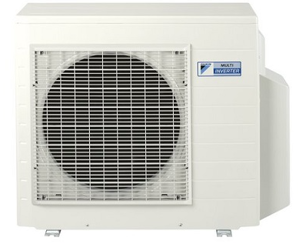


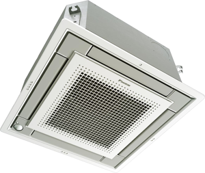

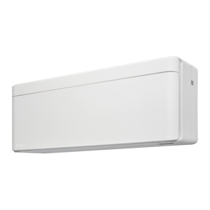
Explore Other Assets


© 2026 MaintainX. All rights reserved.