


Daikin Air Conditioner FTX30NVJU
Need answers fast?
Explore the manual using AI.
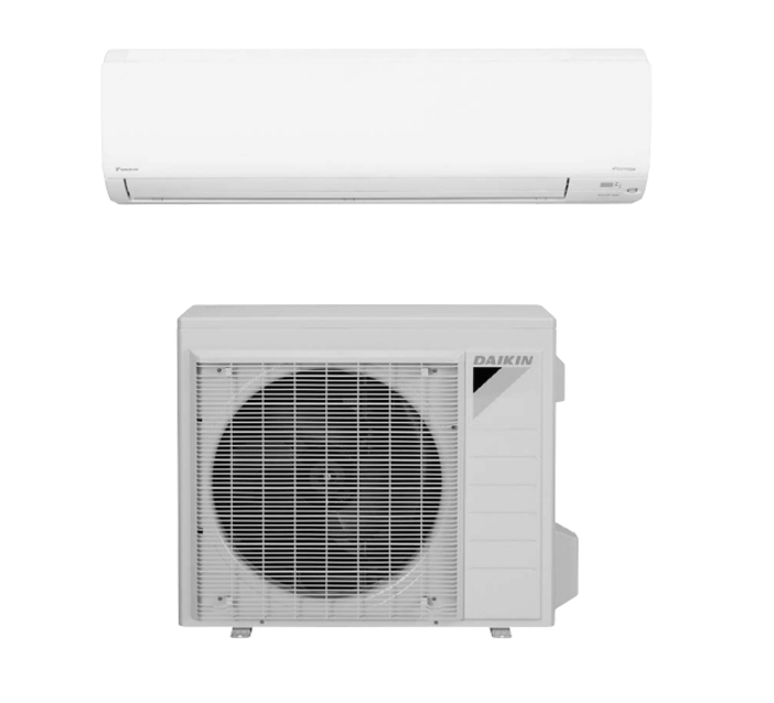
The Daikin Air Conditioner FTX30NVJU is a high-efficiency cooling solution designed for residential and commercial applications. Known for its reliability and advanced technology, this model ensures optimal indoor comfort while minimizing energy consumption. Regular maintenance is essential for peak performance and longevity.
Turn manuals into instant answers
with your AI-powered assistantTurn manuals into instant answers
with your AI-powered assistant
Manual for Daikin Air Conditioner FTX30NVJU
Complete asset maintenance, one click away
Get instant access to all the maintenance information you need. Empower technicians to perform preventive maintenance with asset packages, ready to use right out of the box.

Documents & Manuals
Find all the essential guides in one place.
 Tensioning Guide
- Belt-diagram
- C-120 pulleys
+ 13 more

Work Order Templates
Pre-built workflows to keep your asset running smoothly.
- Daily Electrical System Inspection
- Replace Roller and Pulley
- Install Engine B-120
+ 29 more

Procedures
Integrate maintenance plans directly into your work orders.
- Motion Industries
- Applied Industrial Technologies
- Electrical Brothers
+ 5 more

Parts
Access the parts list for your equipment in MaintainX.
- Drive Motor
- B2 Rollers
- Tensioning System
+ 40 more
Daikin Air Conditioner FTX30NVJU
Create an account to install this asset package.
Maintenance Plans for Daikin Air Conditioner Model FTX30NVJU
Integrate maintenance plans directly into your work orders in MaintainX.
Rotation Pulse Check
Voltage applied (320 + 100 V ~ 320 - 50 V)
Set operation off and power off. Disconnect the connector S70 or S71
Voltage between the pins 4 - 7 (320 VDC)
Control voltage between the pins 4 - 3 (15 VDC)
Rotation command voltage between the pins 4 - 2 (0 ~ 6.5 VDC)
Keep operation off and power off. Connect the connector S70 or S71
Rotation pulses (0 ~ 15 VDC) at the pins 4 - 1 when the fan motor is rotated 1 turn by hand
Sign off on the rotation pulse check

Inverter Analyzer Check
Warning: This procedure requires trained personnel. Always ensure power is off before starting.
Power turned off?
Inverter analyzer installed instead of compressor?
Note: Ensure the charged voltage of the built-in smoothing electrolytic capacitor drops to 10 VDC or below before carrying out the service work.
Enter the charged voltage of the built-in smoothing electrolytic capacitor
Charged voltage dropped to 10 VDC or below?
Power transistor test operation activated from the indoor unit?
Upload a photo of the inverter analyzer setup
Sign off on the inverter analyzer check
Thermistor Resistance Check
Warning: Disconnect the connectors of the thermistors from the PCB before proceeding
Thermistors disconnected from the PCB
Measure the resistance of each thermistor using a multimeter
Note: The room temperature thermistor is soldered on the PCB
Connector to the control PCB disconnected before measuring the resistance
If the connector of indoor heat exchanger thermistor is soldered on the PCB, remove the thermistor
Thermistor removed from the PCB
Measure the resistance of the removed thermistor
Sign off on the thermistor resistance check
Indoor Fan Motor Connector Output Check
Check the connection of connector
Check the motor power supply voltage output
Check the motor control voltage
Check the rotation command voltage
Check the rotation pulse
Sign off on the connector output check
Electronic Expansion Valve Check
Conduct the following to check the electronic expansion valve (EV)
Check if the EV connector is correctly connected to the PCB
Turn the power off and on again, and check to see if the EV generates a latching sound
If the EV does not generate a latching sound in the above step 2, disconnect the connector and check the continuity using a multimeter
Check the continuity between the pins 5 - 1, 5 - 2, 5 - 3, 5 - 4. If there is no continuity between the pins, the EV coil is faulty
If the continuity is confirmed in step 3, the outdoor unit PCB (main PCB) is faulty;
Parts for Daikin Air Conditioner FTX30NVJU
Access the parts list for your equipment in MaintainX.
Inverter Checker
1225477
Inverter Checker
1225477
Inverter Checker
1225477
Unlock efficiency
with MaintainX CoPilot
MaintainX CoPilot is your expert colleague, on call 24/7, helping your team find the answers they need to keep equipment running.
Reduce Unplanned Downtime
Ensure your team follows consistent procedures to minimize equipment failures and costly delays.
Maximize Asset Availability
Keep your assets running longer and more reliably, with standardized maintenance workflows from OEM manuals.
Lower Maintenance Costs
Turn any technician into an expert to streamline operations, maintain more assets, and reduce overall costs.
Thousands of companies manage their assets with MaintainX

'%3e%3cpath%20fill='url(%23b)'%20d='M66.008%2080.068c-5.084-.786-9.763-3.834-12.442-8.68a16.942%2016.942%200%200%201-1.87-5.18c1.096.19%202.203.476%203.298.87%206.525%202.333%2010.836%207.68%2011.014%2012.99ZM51.47%2061.576c.488-5.524%203.62-10.716%208.847-13.597a17.132%2017.132%200%200%201%2011.335-1.882c-.798%208.145-7.43%2014.848-16.038%2015.599-1.417.119-2.799.07-4.144-.12Zm28.564-11.478a17.513%2017.513%200%200%201%203.727%204.62c4.608%208.335%201.584%2018.813-6.75%2023.409a16.988%2016.988%200%200%201-4.359%201.679%2019.624%2019.624%200%200%201-3.977-12.776c.346-7.561%204.942-13.931%2011.36-16.932Z'/%3e%3cpath%20fill='%23110F0D'%20fill-rule='evenodd'%20d='M142.831%2048.324h4.977V77.03h-4.977V48.324Zm27.278%2013.002c.322%201.048.453%202.263.453%203.62v12.073h-4.787V66.208c0-.75-.047-1.572-.154-2.143-.453-2.382-1.822-3.572-4.215-3.572-2.31%200-3.882%201.274-4.43%203.476-.143.596-.226%201.405-.226%202.25v10.8h-4.787V56.623h4.477v2.989c1.536-2.5%203.906-3.43%206.371-3.43%203.488%200%206.263%201.68%207.298%205.144Zm24.636%207.323c0%203.882-2.358%206.525-5.763%207.727-1.298.453-2.632.643-4.62.643h-10.169V48.324h9.085c1.691%200%203.156.143%204.049.38%203.465.93%205.727%203.68%205.727%207.335%200%202.441-.81%204.156-2.762%205.644%202.905%201.417%204.453%203.727%204.453%206.966Zm-15.634-8.656h4.584c1.024%200%201.917-.143%202.536-.417%201.215-.548%201.905-1.608%201.905-3.167%200-1.548-.643-2.572-1.845-3.132-.691-.31-1.762-.452-2.763-.452h-4.417v7.168Zm10.716%208.465c0-1.536-.893-3.37-3.227-3.893-.428-.095-1.036-.143-1.571-.143h-5.918v8.085h5.501c.56%200%201.429-.048%201.953-.167%201.94-.453%203.262-1.846%203.262-3.882Zm47.747-11.847-8.097%2020.408h-4.429l-8.109-20.408h5.191l5.192%2014.574%205.108-14.574h5.144Zm-20.218%2010.002c0%20.69-.036%201.262-.155%201.94h-15.943c.631%202.87%202.714%204.728%205.882%204.728%202.131%200%203.607-.882%204.703-2.525h4.87c-1.762%204.144-5.204%206.692-9.657%206.692-6.084%200-10.537-4.858-10.537-10.49%200-6.108%204.524-10.776%2010.335-10.776%206.239%200%2010.442%204.954%2010.502%2010.43Zm-4.763-1.405c-.333-2.846-2.643-4.858-5.691-4.858-2.894%200-5.287%201.929-5.621%204.858h11.312Zm-72.667%203.44c0%204.787-3.287%208.371-9.419%208.371H119.363V64.66c-1.917.274-3.87.69-5.811%201.238l4.537%2011.121h-5.418l-3.596-9.585c-5.144%202.084-10.085%205.216-14.217%209.585h-4.786L101.8%2048.312h4.56l5.68%2013.883a44.112%2044.112%200%200%201%207.323-1.774V48.312h9.084c1.703%200%203.156.143%204.061.393%203.453.929%205.727%203.667%205.727%207.323%200%201.917-.738%204.179-2.81%205.691%203.06%201.56%204.501%204.025%204.501%206.93Zm-15.634-8.667a62.664%2062.664%200%200%201%202.06-.036c1.703.012%203.239.131%204.608.37%201.441-.549%202.357-1.727%202.357-3.537%200-1.941-.881-3.144-2.488-3.667-.548-.18-1.358-.286-2.322-.286h-4.215v7.156Zm-16.55%203.905-3.715-9.894-6.394%2016.502c2.833-2.595%206.263-4.858%2010.109-6.608Zm27.254%204.74c0-2.775-3.131-4.347-8.513-4.418-.715%200-1.441.011-2.191.047v8.252h5.918c2.548%200%204.786-1.37%204.786-3.882Z'%20clip-rule='evenodd'/%3e%3c/g%3e%3cdefs%3e%3clinearGradient%20id='b'%20x1='51.47'%20x2='85.916'%20y1='62.946'%20y2='62.946'%20gradientUnits='userSpaceOnUse'%3e%3cstop%20stop-color='%23CD9F28'/%3e%3cstop%20offset='1'%20stop-color='%23ECD80B'/%3e%3c/linearGradient%3e%3cclipPath%20id='a'%3e%3cpath%20fill='%23fff'%20d='M51.47%2045.728h186.104V80.14H51.47z'/%3e%3c/clipPath%3e%3c/defs%3e%3c/svg%3e)


More from Daikin


Explore Other Assets


© 2026 MaintainX. All rights reserved.