


Yaskawa F7 Drive CIMR-F7U4075
Need answers fast?
Explore the manual using AI.

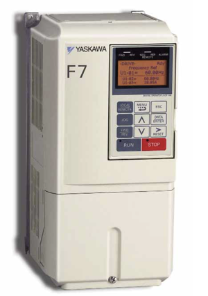
The Yaskawa F7 Drive CIMR-F7U4075 is a high-performance industrial drive designed for precise motor control and energy efficiency. Ideal for various applications, this drive offers advanced features and robust reliability, making it a preferred choice for automation and control systems in industrial settings.
Turn manuals into instant answers
with your AI-powered assistantTurn manuals into instant answers
with your AI-powered assistant
Manual for Yaskawa F7 Drive CIMR-F7U4075
Complete asset maintenance, one click away
Get instant access to all the maintenance information you need. Empower technicians to perform preventive maintenance with asset packages, ready to use right out of the box.

Documents & Manuals
Find all the essential guides in one place.
 Tensioning Guide
- Belt-diagram
- C-120 pulleys
+ 13 more

Work Order Templates
Pre-built workflows to keep your asset running smoothly.
- Daily Electrical System Inspection
- Replace Roller and Pulley
- Install Engine B-120
+ 29 more

Procedures
Integrate maintenance plans directly into your work orders.
- Motion Industries
- Applied Industrial Technologies
- Electrical Brothers
+ 5 more

Parts
Access the parts list for your equipment in MaintainX.
- Drive Motor
- B2 Rollers
- Tensioning System
+ 40 more
Yaskawa F7 Drive CIMR-F7U4075
Create an account to install this asset package.
Maintenance Plans for Yaskawa F7 Drive Model CIMR-F7U4075
Integrate maintenance plans directly into your work orders in MaintainX.
10 Yearly DC Bus and Control Power Fuses Replacement
Warning: This procedure should be performed by a trained technician
Enter the part number of the new DC bus fuse
Enter the part number of the new control power fuse
DC bus fuse replaced successfully
Control power fuse replaced successfully
Enter the ambient temperature
Enter the load factor
Enter the operating time
Technician's signature

1 Yearly F7 Drive Inspection
Warning: This inspection requires trained personnel with PPE!
Inspect conductors and wire connections for loose lugs, screws, wires, hot spots, corrosion, bent conductors, breakage, cracking, discoloration, and spacing
Inspect terminal blocks for looseness or damage
Check DC bus capacitors for leakage, ruptures, expansion, capacitance, and insulation resistance
Inspect relays and contactors for noise and contact discoloration
Check soft charge resistors for cracks and discoloration
Check control circuit operation, including speed reference voltage/current and I/O contact operation
Inspect the Cooling Fans/Fins & Heatsink for loose connectors
Check the digital operator for key functionality, and cleanliness
2 Yearly / 20000 Hourly Cooling Fan Replacement
Warning: This procedure requires trained personnel with PPE!
Replace the cooling fan(s) every 2 to 3 years (20,000 hours) with a new part.
Note: The standard replacement period is based on the following usage conditions:
Ambient temperature
Load factor
Operating time
Was the cooling fan replaced?
Sign off on the cooling fan replacement
3 Monthly F7 Drive Inspection
Check ambient temperature, humidity, dust, harmful gas, and oil mist.
Check for abnormal vibration or noise in the equipment.
Inspect the main circuit and control voltage of the AC power supply.
Check transformers and reactors for discoloration or noise.
Inspect the Cooling Fans/Fins & Heatsink for abnormal fan noise and accumulation.
Check the digital operator for LED functionality, monitor display values.
Note: If the Drive is used under the following conditions, it may be necessary to inspect more often:
Select the conditions under which the Drive is used
5 Yearly Capacitors Replacement
Warning: This procedure requires trained personnel with PPE!
Standard replacement period is based on: Yearly average of 86°F / 30°C, Load factor: 80% maximum, Operating time: 12 hours maximum per day
DC bus capacitors need replacement?
PCB capacitors need replacement?
Soft charge contactor need replacement?
Upload a photo of the replaced parts
Sign off on the capacitors replacement
Parts for Yaskawa F7 Drive CIMR-F7U4075
Access the parts list for your equipment in MaintainX.
Control PCB (1PCB)
ETC618390-S3020
DC Bus Fuse
FU-002112
Diode Module
SID003117
Gate Drive PCB (3PCB)
ETC617190
Heat Sink Fan
FAN001052
Control PCB (1PCB)
ETC618390-S3020
DC Bus Fuse
FU-002112
Diode Module
SID003117
Gate Drive PCB (3PCB)
ETC617190
Heat Sink Fan
FAN001052
Control PCB (1PCB)
ETC618390-S3020
DC Bus Fuse
FU-002112
Diode Module
SID003117
Gate Drive PCB (3PCB)
ETC617190
Heat Sink Fan
FAN001052
Unlock efficiency
with MaintainX CoPilot
MaintainX CoPilot is your expert colleague, on call 24/7, helping your team find the answers they need to keep equipment running.
Reduce Unplanned Downtime
Ensure your team follows consistent procedures to minimize equipment failures and costly delays.
Maximize Asset Availability
Keep your assets running longer and more reliably, with standardized maintenance workflows from OEM manuals.
Lower Maintenance Costs
Turn any technician into an expert to streamline operations, maintain more assets, and reduce overall costs.
Thousands of companies manage their assets with MaintainX

'%3e%3cpath%20fill='url(%23b)'%20d='M66.008%2080.068c-5.084-.786-9.763-3.834-12.442-8.68a16.942%2016.942%200%200%201-1.87-5.18c1.096.19%202.203.476%203.298.87%206.525%202.333%2010.836%207.68%2011.014%2012.99ZM51.47%2061.576c.488-5.524%203.62-10.716%208.847-13.597a17.132%2017.132%200%200%201%2011.335-1.882c-.798%208.145-7.43%2014.848-16.038%2015.599-1.417.119-2.799.07-4.144-.12Zm28.564-11.478a17.513%2017.513%200%200%201%203.727%204.62c4.608%208.335%201.584%2018.813-6.75%2023.409a16.988%2016.988%200%200%201-4.359%201.679%2019.624%2019.624%200%200%201-3.977-12.776c.346-7.561%204.942-13.931%2011.36-16.932Z'/%3e%3cpath%20fill='%23110F0D'%20fill-rule='evenodd'%20d='M142.831%2048.324h4.977V77.03h-4.977V48.324Zm27.278%2013.002c.322%201.048.453%202.263.453%203.62v12.073h-4.787V66.208c0-.75-.047-1.572-.154-2.143-.453-2.382-1.822-3.572-4.215-3.572-2.31%200-3.882%201.274-4.43%203.476-.143.596-.226%201.405-.226%202.25v10.8h-4.787V56.623h4.477v2.989c1.536-2.5%203.906-3.43%206.371-3.43%203.488%200%206.263%201.68%207.298%205.144Zm24.636%207.323c0%203.882-2.358%206.525-5.763%207.727-1.298.453-2.632.643-4.62.643h-10.169V48.324h9.085c1.691%200%203.156.143%204.049.38%203.465.93%205.727%203.68%205.727%207.335%200%202.441-.81%204.156-2.762%205.644%202.905%201.417%204.453%203.727%204.453%206.966Zm-15.634-8.656h4.584c1.024%200%201.917-.143%202.536-.417%201.215-.548%201.905-1.608%201.905-3.167%200-1.548-.643-2.572-1.845-3.132-.691-.31-1.762-.452-2.763-.452h-4.417v7.168Zm10.716%208.465c0-1.536-.893-3.37-3.227-3.893-.428-.095-1.036-.143-1.571-.143h-5.918v8.085h5.501c.56%200%201.429-.048%201.953-.167%201.94-.453%203.262-1.846%203.262-3.882Zm47.747-11.847-8.097%2020.408h-4.429l-8.109-20.408h5.191l5.192%2014.574%205.108-14.574h5.144Zm-20.218%2010.002c0%20.69-.036%201.262-.155%201.94h-15.943c.631%202.87%202.714%204.728%205.882%204.728%202.131%200%203.607-.882%204.703-2.525h4.87c-1.762%204.144-5.204%206.692-9.657%206.692-6.084%200-10.537-4.858-10.537-10.49%200-6.108%204.524-10.776%2010.335-10.776%206.239%200%2010.442%204.954%2010.502%2010.43Zm-4.763-1.405c-.333-2.846-2.643-4.858-5.691-4.858-2.894%200-5.287%201.929-5.621%204.858h11.312Zm-72.667%203.44c0%204.787-3.287%208.371-9.419%208.371H119.363V64.66c-1.917.274-3.87.69-5.811%201.238l4.537%2011.121h-5.418l-3.596-9.585c-5.144%202.084-10.085%205.216-14.217%209.585h-4.786L101.8%2048.312h4.56l5.68%2013.883a44.112%2044.112%200%200%201%207.323-1.774V48.312h9.084c1.703%200%203.156.143%204.061.393%203.453.929%205.727%203.667%205.727%207.323%200%201.917-.738%204.179-2.81%205.691%203.06%201.56%204.501%204.025%204.501%206.93Zm-15.634-8.667a62.664%2062.664%200%200%201%202.06-.036c1.703.012%203.239.131%204.608.37%201.441-.549%202.357-1.727%202.357-3.537%200-1.941-.881-3.144-2.488-3.667-.548-.18-1.358-.286-2.322-.286h-4.215v7.156Zm-16.55%203.905-3.715-9.894-6.394%2016.502c2.833-2.595%206.263-4.858%2010.109-6.608Zm27.254%204.74c0-2.775-3.131-4.347-8.513-4.418-.715%200-1.441.011-2.191.047v8.252h5.918c2.548%200%204.786-1.37%204.786-3.882Z'%20clip-rule='evenodd'/%3e%3c/g%3e%3cdefs%3e%3clinearGradient%20id='b'%20x1='51.47'%20x2='85.916'%20y1='62.946'%20y2='62.946'%20gradientUnits='userSpaceOnUse'%3e%3cstop%20stop-color='%23CD9F28'/%3e%3cstop%20offset='1'%20stop-color='%23ECD80B'/%3e%3c/linearGradient%3e%3cclipPath%20id='a'%3e%3cpath%20fill='%23fff'%20d='M51.47%2045.728h186.104V80.14H51.47z'/%3e%3c/clipPath%3e%3c/defs%3e%3c/svg%3e)


More from Yaskawa


Explore Other Assets


© 2026 MaintainX. All rights reserved.