


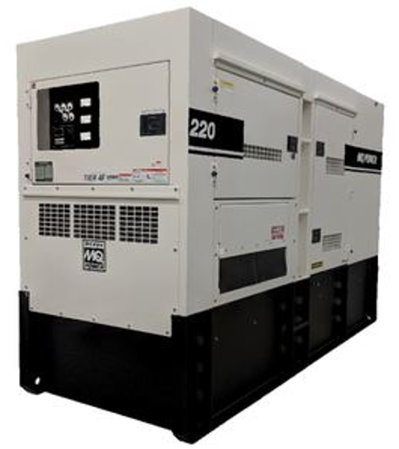
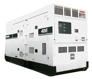
Multiquip Portable Generator DCA220SSJU4F3
Need answers fast?
Explore the manual using AI.
Turn manuals into instant answers
with your AI-powered assistantTurn manuals into instant answers
with your AI-powered assistant
Manual for Multiquip Portable Generator DCA220SSJU4F3
Complete asset maintenance, one click away
Get instant access to all the maintenance information you need. Empower technicians to perform preventive maintenance with asset packages, ready to use right out of the box.

Documents & Manuals
Find all the essential guides in one place.
 Tensioning Guide
- Belt-diagram
- C-120 pulleys
+ 13 more

Work Order Templates
Pre-built workflows to keep your asset running smoothly.
- Daily Electrical System Inspection
- Replace Roller and Pulley
- Install Engine B-120
+ 29 more

Procedures
Integrate maintenance plans directly into your work orders.
- Motion Industries
- Applied Industrial Technologies
- Electrical Brothers
+ 5 more

Parts
Access the parts list for your equipment in MaintainX.
- Drive Motor
- B2 Rollers
- Tensioning System
+ 40 more
Multiquip Portable Generator DCA220SSJU4F3
Create an account to install this asset package.
Maintenance Plans for Multiquip Portable Generator Model DCA220SSJU4F3
Integrate maintenance plans directly into your work orders in MaintainX.
Relay Base Holder Maintenance
Warning: This procedure requires trained personnel with PPE!
Fuel pump relay tested normal?
If fuel pump relay did not test normal, report the issue to the maintenance team and stop the procedure
Is the generator model between DCA6 and DCA125?
If the generator model is not between DCA6 and DCA125, report the issue to the maintenance team and stop the procedure
Is the fuel pump relay base holder not a ‘sealed type’?
If the fuel pump relay base holder is a ‘sealed type’, report the issue to the maintenance team and stop the procedure
Is there corrosion and dirt in the fuel pump relay base holder?
If there is no corrosion and dirt in the fuel pump relay base holder, report the issue to the maintenance team and stop the procedure

Manual Excitation Test
MANUAL EXCITATION TEST (3-PHASE VOLTAGE):
1. With the engine OFF, place the voltage selector switch (Figure 39A) in the 3-Phase, 240/139V position.
2. Unplug the 6-pin plug from the CN1 receptacle on the AVR (Figure 39B).
3. Connect a SPST toggle switch (Figure 39C) between the positive battery terminal and pin J on the 6-pin plug.
4. Connect a wire from the negative battery terminal to pin K on the 6-pin plug (Figure 39D).
5. Place toggle switch in the OFF (open) position, if equipped set engine speed switch to the low position (idle). Start the engine and then place toggle switch in ON position (closed).
6. Next, place engine speed switch in the high position and run the engine at full rpm.
7. Place the selection dial on the multimeter to the AC volts position (Figure 39E).
8. Using; a multimeter, measure voltage at the U, V and W terminals (Figure 39F) located on top of the main circuit breaker (line side).
Mpu Ac Voltage Test
Warning: This procedure requires trained personnel with PPE!
Multimeter test leads placed across pins 1 and 2 on the ECU auto-start module
Enter the multimeter reading
Is the multimeter reading between 2.25 VAC ± 0.50?
If a low voltage reading is obtained, reference the 'MPU Installation and Adjustment' section.
Sign off on the Mpu Ac Voltage Test
Main Armature Avr Inputs Resistance Check
NOTICE: Before performing the resistance check, the 6-pin plug (Figure 51B) must be disconnected from the CN1 receptacle on the AVR. If the reading indicates an open circuit the component may have to be replaced or repaired.
6-pin plug disconnected from the CN1 receptacle on the AVR?
Set the multimeter selection dial to the W position as shown in Figure 51A.
Check the resistance across the A-B, C-D, D-A open delta wire leads as referenced in Figure 51B. Compare measured reading to values listed in Table 6, column E.
Check the resistance across the B-C open delta wire leads as referenced in Figure 51B. Compare measured reading to values listed in Table 6, column F.
6-pin plug disconnected from the CN1 receptacle on the AVR again?
As shown in Figure 52 there are three outside connectors that plug into the CN1, CN3 and CN4 receptacles on the AVR.
The CN2 receptacle has no outside plug connected to it. Pins 1 and 2 are internally jumpered together and pins 3 and 4 are also jumpered together.
As shown in Figure 52 there are two WHITE wires that connect to the AVR 2-pin terminal block via relay unit RY1.
Mpu Adjustment
Loosen the jam nut that secures the MPU to the sensor plate
Remove MPU
Visually view the flywheel teeth through the hole opening on the sensor plate
Attach a ratchet to the crankshaft pulley and rotate the flywheel gear until the highest point of the flywheel gear tooth is visible
Reinstall the MPU sensor back into the sensor plate. Continue screwing the MPU sensor clockwise until contact is made with the flywheel gear tooth
After making contact with the flywheel gear tooth, unscrew the MPU sensor counterclockwise 1/2 turn
Verify that the MPU sensor does not make contact with the flywheel by rotating the flywheel gear completely around. Flywheel should rotate freely
The MPU sensor-flywheel gear gap should be adjusted so that the minimum voltage required is attained while the engine is in crank status. The voltage setting we are looking to obtain is 2.25 VAC +/- 0.50 VAC
Once the correct gap is obtained, tighten the MPU sensor jam nut to secure it to the sensor plate
Parts for Multiquip Portable Generator DCA220SSJU4F3
Access the parts list for your equipment in MaintainX.
Output Terminal Bolt
M9220100304A
Tie Bolt 62.7 N.M
M9220100404
Change-Over Board Bolt
M9220100104
Output Terminal Bolt
M9220100304A
Tie Bolt 62.7 N.M
M9220100404
Change-Over Board Bolt
M9220100104
Output Terminal Bolt
M9220100304A
Tie Bolt 62.7 N.M
M9220100404
Change-Over Board Bolt
M9220100104
Unlock efficiency
with MaintainX CoPilot
MaintainX CoPilot is your expert colleague, on call 24/7, helping your team find the answers they need to keep equipment running.
Reduce Unplanned Downtime
Ensure your team follows consistent procedures to minimize equipment failures and costly delays.
Maximize Asset Availability
Keep your assets running longer and more reliably, with standardized maintenance workflows from OEM manuals.
Lower Maintenance Costs
Turn any technician into an expert to streamline operations, maintain more assets, and reduce overall costs.
Thousands of companies manage their assets with MaintainX

'%3e%3cpath%20fill='url(%23b)'%20d='M66.008%2080.068c-5.084-.786-9.763-3.834-12.442-8.68a16.942%2016.942%200%200%201-1.87-5.18c1.096.19%202.203.476%203.298.87%206.525%202.333%2010.836%207.68%2011.014%2012.99ZM51.47%2061.576c.488-5.524%203.62-10.716%208.847-13.597a17.132%2017.132%200%200%201%2011.335-1.882c-.798%208.145-7.43%2014.848-16.038%2015.599-1.417.119-2.799.07-4.144-.12Zm28.564-11.478a17.513%2017.513%200%200%201%203.727%204.62c4.608%208.335%201.584%2018.813-6.75%2023.409a16.988%2016.988%200%200%201-4.359%201.679%2019.624%2019.624%200%200%201-3.977-12.776c.346-7.561%204.942-13.931%2011.36-16.932Z'/%3e%3cpath%20fill='%23110F0D'%20fill-rule='evenodd'%20d='M142.831%2048.324h4.977V77.03h-4.977V48.324Zm27.278%2013.002c.322%201.048.453%202.263.453%203.62v12.073h-4.787V66.208c0-.75-.047-1.572-.154-2.143-.453-2.382-1.822-3.572-4.215-3.572-2.31%200-3.882%201.274-4.43%203.476-.143.596-.226%201.405-.226%202.25v10.8h-4.787V56.623h4.477v2.989c1.536-2.5%203.906-3.43%206.371-3.43%203.488%200%206.263%201.68%207.298%205.144Zm24.636%207.323c0%203.882-2.358%206.525-5.763%207.727-1.298.453-2.632.643-4.62.643h-10.169V48.324h9.085c1.691%200%203.156.143%204.049.38%203.465.93%205.727%203.68%205.727%207.335%200%202.441-.81%204.156-2.762%205.644%202.905%201.417%204.453%203.727%204.453%206.966Zm-15.634-8.656h4.584c1.024%200%201.917-.143%202.536-.417%201.215-.548%201.905-1.608%201.905-3.167%200-1.548-.643-2.572-1.845-3.132-.691-.31-1.762-.452-2.763-.452h-4.417v7.168Zm10.716%208.465c0-1.536-.893-3.37-3.227-3.893-.428-.095-1.036-.143-1.571-.143h-5.918v8.085h5.501c.56%200%201.429-.048%201.953-.167%201.94-.453%203.262-1.846%203.262-3.882Zm47.747-11.847-8.097%2020.408h-4.429l-8.109-20.408h5.191l5.192%2014.574%205.108-14.574h5.144Zm-20.218%2010.002c0%20.69-.036%201.262-.155%201.94h-15.943c.631%202.87%202.714%204.728%205.882%204.728%202.131%200%203.607-.882%204.703-2.525h4.87c-1.762%204.144-5.204%206.692-9.657%206.692-6.084%200-10.537-4.858-10.537-10.49%200-6.108%204.524-10.776%2010.335-10.776%206.239%200%2010.442%204.954%2010.502%2010.43Zm-4.763-1.405c-.333-2.846-2.643-4.858-5.691-4.858-2.894%200-5.287%201.929-5.621%204.858h11.312Zm-72.667%203.44c0%204.787-3.287%208.371-9.419%208.371H119.363V64.66c-1.917.274-3.87.69-5.811%201.238l4.537%2011.121h-5.418l-3.596-9.585c-5.144%202.084-10.085%205.216-14.217%209.585h-4.786L101.8%2048.312h4.56l5.68%2013.883a44.112%2044.112%200%200%201%207.323-1.774V48.312h9.084c1.703%200%203.156.143%204.061.393%203.453.929%205.727%203.667%205.727%207.323%200%201.917-.738%204.179-2.81%205.691%203.06%201.56%204.501%204.025%204.501%206.93Zm-15.634-8.667a62.664%2062.664%200%200%201%202.06-.036c1.703.012%203.239.131%204.608.37%201.441-.549%202.357-1.727%202.357-3.537%200-1.941-.881-3.144-2.488-3.667-.548-.18-1.358-.286-2.322-.286h-4.215v7.156Zm-16.55%203.905-3.715-9.894-6.394%2016.502c2.833-2.595%206.263-4.858%2010.109-6.608Zm27.254%204.74c0-2.775-3.131-4.347-8.513-4.418-.715%200-1.441.011-2.191.047v8.252h5.918c2.548%200%204.786-1.37%204.786-3.882Z'%20clip-rule='evenodd'/%3e%3c/g%3e%3cdefs%3e%3clinearGradient%20id='b'%20x1='51.47'%20x2='85.916'%20y1='62.946'%20y2='62.946'%20gradientUnits='userSpaceOnUse'%3e%3cstop%20stop-color='%23CD9F28'/%3e%3cstop%20offset='1'%20stop-color='%23ECD80B'/%3e%3c/linearGradient%3e%3cclipPath%20id='a'%3e%3cpath%20fill='%23fff'%20d='M51.47%2045.728h186.104V80.14H51.47z'/%3e%3c/clipPath%3e%3c/defs%3e%3c/svg%3e)


More from Multiquip


Explore Other Assets


© 2026 MaintainX. All rights reserved.