


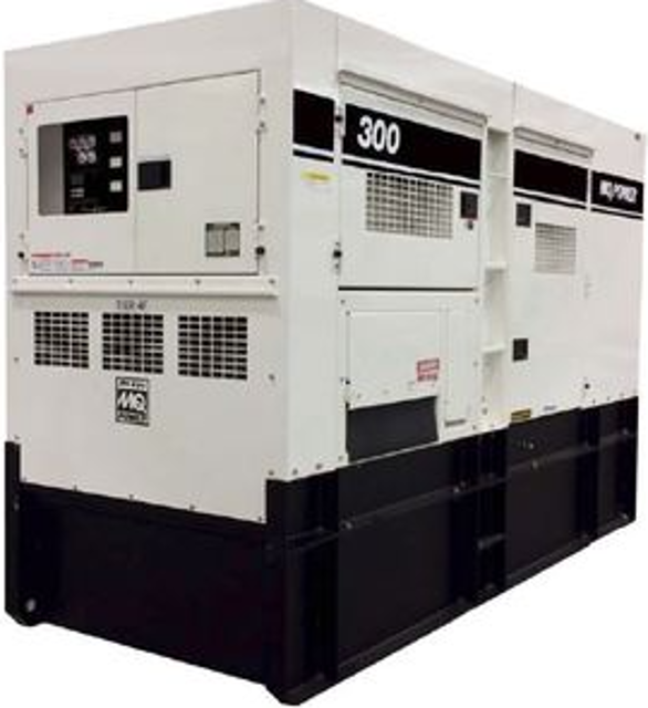
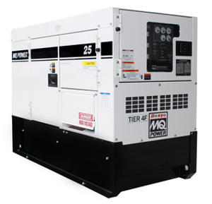
Multiquip Portable Generator DCA300SSJU4F3
Need answers fast?
Explore the manual using AI.
Turn manuals into instant answers
with your AI-powered assistantTurn manuals into instant answers
with your AI-powered assistant
Manual for Multiquip Portable Generator DCA300SSJU4F3
Complete asset maintenance, one click away
Get instant access to all the maintenance information you need. Empower technicians to perform preventive maintenance with asset packages, ready to use right out of the box.

Documents & Manuals
Find all the essential guides in one place.
 Tensioning Guide
- Belt-diagram
- C-120 pulleys
+ 13 more

Work Order Templates
Pre-built workflows to keep your asset running smoothly.
- Daily Electrical System Inspection
- Replace Roller and Pulley
- Install Engine B-120
+ 29 more

Procedures
Integrate maintenance plans directly into your work orders.
- Motion Industries
- Applied Industrial Technologies
- Electrical Brothers
+ 5 more

Parts
Access the parts list for your equipment in MaintainX.
- Drive Motor
- B2 Rollers
- Tensioning System
+ 40 more
Multiquip Portable Generator DCA300SSJU4F3
Create an account to install this asset package.
Maintenance Plans for Multiquip Portable Generator Model DCA300SSJU4F3
Integrate maintenance plans directly into your work orders in MaintainX.
Engine Overspeed Adjustment
NOTICE: Be sure you have adjusted the engine crank disconnect potentiometer first.
Turn the engine overspeed adjustment potentiometer (Figure 56C) 30 turns clockwise
Using a small, flat-blade screwdriver, set the DIP switch at position 5 (Figure 56D) to the ON position (up)
Start the engine. It should crank and start. Verify that the engine running LED is lit.
Now start turning the overspeed adjustment potentiometer counterclockwise until the engine control shuts down the engine (overspeed fault)
Again using a small, flat-blade screwdriver, set the DIP switch at position 5 to the OFF position (down)
If the overcrank and overspeed LEDs light at the same time on the ECU, reference troubleshooting flow charts in this service manual for additional information.
Sign off on the engine overspeed adjustment

Mpu Adjustment
Loosen the jam nut that secures the MPU to the sensor plate
Remove MPU
Visually view the flywheel teeth through the hole opening on the sensor plate
Attach a ratchet to the crankshaft pulley and rotate the flywheel gear until the highest point of the flywheel gear tooth is visible
Reinstall the MPU sensor back into the sensor plate. Continue screwing the MPU sensor clockwise until contact is made with the flywheel gear tooth
After making contact with the flywheel gear tooth, unscrew the MPU sensor counterclockwise 1/2 turn
Verify that the MPU sensor does not make contact with the flywheel by rotating the flywheel gear completely around. Flywheel should rotate freely
The MPU sensor-flywheel gear gap should be adjusted so that the minimum voltage required is attained while the engine is in crank status. The voltage setting we are looking to obtain is 2.25 VAC +/- 0.50 VAC
Once the correct gap is obtained, tighten the MPU sensor jam nut to secure it to the sensor plate
Main Field Resistance Test
NOTICE: Before performing the resistance test, the two black lead wires (Figure 36) must be disconnected from the rotating rectifier.
The main field (Figure 36) consists of two black lead wires with no wire designation. These two wire leads are connected to the DC positive and DC negative terminals on the rotating rectifier in conjunction with the surge protector.
Have the two black lead wires been disconnected from the rotating rectifier?
Upload a photo of the disconnected wires
Using a multimeter (Figure 36), enter the resistance across each black wire as referenced in Table 6, column B.
Does the multimeter reading indicate an open circuit?
If the reading indicates an open circuit, describe the component that may have to be replaced or repaired.
Sign off on the Main Field Resistance Test
Relay Base Holder Maintenance
Warning: This procedure requires trained personnel with PPE!
Fuel pump relay tested normal?
If fuel pump relay did not test normal, report the issue to the maintenance team and stop the procedure
Is the relay base holder a 'sealed type'?
If the relay base holder is a 'sealed type', report the issue to the maintenance team and stop the procedure
Cleaning of the relay base holder
Fuel pump relay removed from its base holder?
Dielectric cleaner sprayed onto the contact pins on the relay base holder?
Enter the air pressure used to blow off any dirt and debris
Generator Inspection
Cable ends, wire connectors and terminals, tighten and repair as needed
Generator end for signs of heat discoloration
Panel controls and breakers for signs of heat discoloration and that they are securely mounted
All gauges for proper operation during test run
Frequency and voltage, adjust as necessary
Sign off on the generator inspection
Parts for Multiquip Portable Generator DCA300SSJU4F3
Access the parts list for your equipment in MaintainX.
Output Terminal Bolt
M9220100914
Tie Bolt 123.0 N.M
M9220101004
Change-Over Board Bolt
M9220101104
Output Terminal Bolt
M9220100914
Tie Bolt 123.0 N.M
M9220101004
Change-Over Board Bolt
M9220101104
Output Terminal Bolt
M9220100914
Tie Bolt 123.0 N.M
M9220101004
Change-Over Board Bolt
M9220101104
Unlock efficiency
with MaintainX CoPilot
MaintainX CoPilot is your expert colleague, on call 24/7, helping your team find the answers they need to keep equipment running.
Reduce Unplanned Downtime
Ensure your team follows consistent procedures to minimize equipment failures and costly delays.
Maximize Asset Availability
Keep your assets running longer and more reliably, with standardized maintenance workflows from OEM manuals.
Lower Maintenance Costs
Turn any technician into an expert to streamline operations, maintain more assets, and reduce overall costs.
Thousands of companies manage their assets with MaintainX

'%3e%3cpath%20fill='url(%23b)'%20d='M66.008%2080.068c-5.084-.786-9.763-3.834-12.442-8.68a16.942%2016.942%200%200%201-1.87-5.18c1.096.19%202.203.476%203.298.87%206.525%202.333%2010.836%207.68%2011.014%2012.99ZM51.47%2061.576c.488-5.524%203.62-10.716%208.847-13.597a17.132%2017.132%200%200%201%2011.335-1.882c-.798%208.145-7.43%2014.848-16.038%2015.599-1.417.119-2.799.07-4.144-.12Zm28.564-11.478a17.513%2017.513%200%200%201%203.727%204.62c4.608%208.335%201.584%2018.813-6.75%2023.409a16.988%2016.988%200%200%201-4.359%201.679%2019.624%2019.624%200%200%201-3.977-12.776c.346-7.561%204.942-13.931%2011.36-16.932Z'/%3e%3cpath%20fill='%23110F0D'%20fill-rule='evenodd'%20d='M142.831%2048.324h4.977V77.03h-4.977V48.324Zm27.278%2013.002c.322%201.048.453%202.263.453%203.62v12.073h-4.787V66.208c0-.75-.047-1.572-.154-2.143-.453-2.382-1.822-3.572-4.215-3.572-2.31%200-3.882%201.274-4.43%203.476-.143.596-.226%201.405-.226%202.25v10.8h-4.787V56.623h4.477v2.989c1.536-2.5%203.906-3.43%206.371-3.43%203.488%200%206.263%201.68%207.298%205.144Zm24.636%207.323c0%203.882-2.358%206.525-5.763%207.727-1.298.453-2.632.643-4.62.643h-10.169V48.324h9.085c1.691%200%203.156.143%204.049.38%203.465.93%205.727%203.68%205.727%207.335%200%202.441-.81%204.156-2.762%205.644%202.905%201.417%204.453%203.727%204.453%206.966Zm-15.634-8.656h4.584c1.024%200%201.917-.143%202.536-.417%201.215-.548%201.905-1.608%201.905-3.167%200-1.548-.643-2.572-1.845-3.132-.691-.31-1.762-.452-2.763-.452h-4.417v7.168Zm10.716%208.465c0-1.536-.893-3.37-3.227-3.893-.428-.095-1.036-.143-1.571-.143h-5.918v8.085h5.501c.56%200%201.429-.048%201.953-.167%201.94-.453%203.262-1.846%203.262-3.882Zm47.747-11.847-8.097%2020.408h-4.429l-8.109-20.408h5.191l5.192%2014.574%205.108-14.574h5.144Zm-20.218%2010.002c0%20.69-.036%201.262-.155%201.94h-15.943c.631%202.87%202.714%204.728%205.882%204.728%202.131%200%203.607-.882%204.703-2.525h4.87c-1.762%204.144-5.204%206.692-9.657%206.692-6.084%200-10.537-4.858-10.537-10.49%200-6.108%204.524-10.776%2010.335-10.776%206.239%200%2010.442%204.954%2010.502%2010.43Zm-4.763-1.405c-.333-2.846-2.643-4.858-5.691-4.858-2.894%200-5.287%201.929-5.621%204.858h11.312Zm-72.667%203.44c0%204.787-3.287%208.371-9.419%208.371H119.363V64.66c-1.917.274-3.87.69-5.811%201.238l4.537%2011.121h-5.418l-3.596-9.585c-5.144%202.084-10.085%205.216-14.217%209.585h-4.786L101.8%2048.312h4.56l5.68%2013.883a44.112%2044.112%200%200%201%207.323-1.774V48.312h9.084c1.703%200%203.156.143%204.061.393%203.453.929%205.727%203.667%205.727%207.323%200%201.917-.738%204.179-2.81%205.691%203.06%201.56%204.501%204.025%204.501%206.93Zm-15.634-8.667a62.664%2062.664%200%200%201%202.06-.036c1.703.012%203.239.131%204.608.37%201.441-.549%202.357-1.727%202.357-3.537%200-1.941-.881-3.144-2.488-3.667-.548-.18-1.358-.286-2.322-.286h-4.215v7.156Zm-16.55%203.905-3.715-9.894-6.394%2016.502c2.833-2.595%206.263-4.858%2010.109-6.608Zm27.254%204.74c0-2.775-3.131-4.347-8.513-4.418-.715%200-1.441.011-2.191.047v8.252h5.918c2.548%200%204.786-1.37%204.786-3.882Z'%20clip-rule='evenodd'/%3e%3c/g%3e%3cdefs%3e%3clinearGradient%20id='b'%20x1='51.47'%20x2='85.916'%20y1='62.946'%20y2='62.946'%20gradientUnits='userSpaceOnUse'%3e%3cstop%20stop-color='%23CD9F28'/%3e%3cstop%20offset='1'%20stop-color='%23ECD80B'/%3e%3c/linearGradient%3e%3cclipPath%20id='a'%3e%3cpath%20fill='%23fff'%20d='M51.47%2045.728h186.104V80.14H51.47z'/%3e%3c/clipPath%3e%3c/defs%3e%3c/svg%3e)


More from Multiquip


Explore Other Assets


© 2026 MaintainX. All rights reserved.