


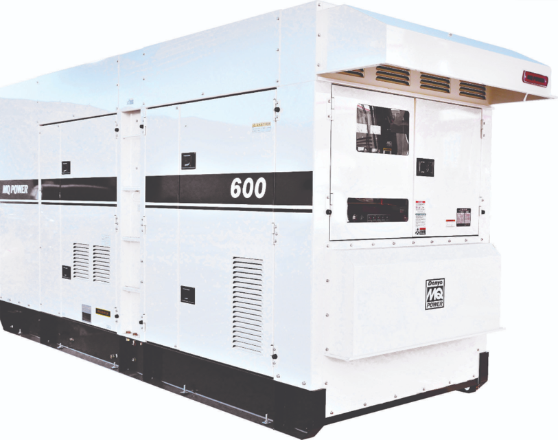
Multiquip Portable Generator DCA600SSV4F3
Need answers fast?
Explore the manual using AI.
Turn manuals into instant answers
with your AI-powered assistantTurn manuals into instant answers
with your AI-powered assistant
Manual for Multiquip Portable Generator DCA600SSV4F3
Complete asset maintenance, one click away
Get instant access to all the maintenance information you need. Empower technicians to perform preventive maintenance with asset packages, ready to use right out of the box.

Documents & Manuals
Find all the essential guides in one place.
 Tensioning Guide
- Belt-diagram
- C-120 pulleys
+ 13 more

Work Order Templates
Pre-built workflows to keep your asset running smoothly.
- Daily Electrical System Inspection
- Replace Roller and Pulley
- Install Engine B-120
+ 29 more

Procedures
Integrate maintenance plans directly into your work orders.
- Motion Industries
- Applied Industrial Technologies
- Electrical Brothers
+ 5 more

Parts
Access the parts list for your equipment in MaintainX.
- Drive Motor
- B2 Rollers
- Tensioning System
+ 40 more
Multiquip Portable Generator DCA600SSV4F3
Create an account to install this asset package.
Maintenance Plans for Multiquip Portable Generator Model DCA600SSV4F3
Integrate maintenance plans directly into your work orders in MaintainX.
Mpu Adjustment
Loosen the jam nut that secures the MPU to the sensor plate
Remove MPU
Visually view the flywheel teeth through the hole opening on the sensor plate
Attach a ratchet to the crankshaft pulley and rotate the flywheel gear until the highest point of the flywheel gear tooth is visible
Reinstall the MPU sensor back into the sensor plate. Continue screwing the MPU sensor clockwise until contact is made with the flywheel gear tooth
After making contact with the flywheel gear tooth, unscrew the MPU sensor counterclockwise 1/2 turn
Verify that the MPU sensor does not make contact with the flywheel by rotating the flywheel gear completely around. Flywheel should rotate freely
The MPU sensor-flywheel gear gap should be adjusted so that the minimum voltage required is attained while the engine is in crank status. The voltage setting we are looking to obtain is 2.25 VAC +/- 0.50 VAC
Once the correct gap is obtained, tighten the MPU sensor jam nut to secure it to the sensor plate

Engine Crank Disconnect Adjustment
Warning: This adjustment requires trained personnel with PPE!
Do you have a small, flat-blade screwdriver?
Turn the engine crank disconnect adjustment potentiometer 30 turns counterclockwise
Turn the engine crank disconnect adjustment potentiometer about 3 turns clockwise
Try to start the engine. Did the starter crank but disengage quickly?
If the engine starts, is the ECU engine running lamp lit?
Once verified, did you shutdown the engine?
With the engine shutdown, adjust the the engine crank disconnect adjustment potentiometer 1 turn clockwise
Try restarting the engine. Did the engine start reliably?
Manual Excitation Test
3-PHASE VOLTAGE TEST
Engine OFF and voltage selector switch in the 3-Phase, 240/139V position
6-pin plug unplugged from the CN1 receptacle on the AVR
SPST toggle switch connected between the positive battery terminal and pin J on the 6-pin plug
Wire connected from the negative battery terminal to pin K on the 6-pin plug
Toggle switch in the OFF position, engine speed switch set to low position, engine started, and toggle switch placed in ON position
Engine speed switch in the high position and engine running at full rpm
Selection dial on the multimeter set to the AC volts position
Voltage at the U, V and W terminals on top of the main circuit breaker
Mpu Ac Voltage Test
Warning: This procedure requires trained personnel with PPE!
Multimeter test leads placed across pins 1 and 2 on the ECU auto-start module
Enter the multimeter reading
Multimeter reading between 2.25 VAC ± 0.50
If a low voltage reading is obtained, reference the 'MPU Installation and Adjustment' section
Sign off on the Mpu Ac Voltage Test
Rotating Rectifier Test
NOTICE: Before performing the continuity test, all lead wires (Figure 48) must be disconnected from the rectifier.
The rotating rectifier is connected to both the main field and exciter armature and is mounted on the exciter stator armature.
Is the selection dial on the multimeter in the diode position?
Did you place the positive lead from the multimeter on the DC POSTIVE (+) terminal of the rectifier (Figure 48)?
Did you touch the U, V and W terminals one at a time with the NEGATIVE (–) lead?
Did each terminal give a continuity reading?
Did you reverse the multimeter leads?
Did you place the NEGATIVE lead of the multimeter on the DC Positive (+) terminal of the rectifier (Figure 49)?
Did you touch U, V and W terminals with the positive lead?
Parts for Multiquip Portable Generator DCA600SSV4F3
Access the parts list for your equipment in MaintainX.
Output Terminal Bolt
Y0010112040
Output Terminal Bolt
W0801830404B
Tie Bolt (Nut) 25.0 N.M
Y0041212000
Tie Bolt 123.0 N.M
M9220101004
Change-Over Board Bolt
W0801832504
Output Terminal Bolt
Y0010112040
Output Terminal Bolt
W0801830404B
Tie Bolt (Nut) 25.0 N.M
Y0041212000
Tie Bolt 123.0 N.M
M9220101004
Change-Over Board Bolt
W0801832504
Output Terminal Bolt
Y0010112040
Output Terminal Bolt
W0801830404B
Tie Bolt (Nut) 25.0 N.M
Y0041212000
Tie Bolt 123.0 N.M
M9220101004
Change-Over Board Bolt
W0801832504
Unlock efficiency
with MaintainX CoPilot
MaintainX CoPilot is your expert colleague, on call 24/7, helping your team find the answers they need to keep equipment running.
Reduce Unplanned Downtime
Ensure your team follows consistent procedures to minimize equipment failures and costly delays.
Maximize Asset Availability
Keep your assets running longer and more reliably, with standardized maintenance workflows from OEM manuals.
Lower Maintenance Costs
Turn any technician into an expert to streamline operations, maintain more assets, and reduce overall costs.
Thousands of companies manage their assets with MaintainX

'%3e%3cpath%20fill='url(%23b)'%20d='M66.008%2080.068c-5.084-.786-9.763-3.834-12.442-8.68a16.942%2016.942%200%200%201-1.87-5.18c1.096.19%202.203.476%203.298.87%206.525%202.333%2010.836%207.68%2011.014%2012.99ZM51.47%2061.576c.488-5.524%203.62-10.716%208.847-13.597a17.132%2017.132%200%200%201%2011.335-1.882c-.798%208.145-7.43%2014.848-16.038%2015.599-1.417.119-2.799.07-4.144-.12Zm28.564-11.478a17.513%2017.513%200%200%201%203.727%204.62c4.608%208.335%201.584%2018.813-6.75%2023.409a16.988%2016.988%200%200%201-4.359%201.679%2019.624%2019.624%200%200%201-3.977-12.776c.346-7.561%204.942-13.931%2011.36-16.932Z'/%3e%3cpath%20fill='%23110F0D'%20fill-rule='evenodd'%20d='M142.831%2048.324h4.977V77.03h-4.977V48.324Zm27.278%2013.002c.322%201.048.453%202.263.453%203.62v12.073h-4.787V66.208c0-.75-.047-1.572-.154-2.143-.453-2.382-1.822-3.572-4.215-3.572-2.31%200-3.882%201.274-4.43%203.476-.143.596-.226%201.405-.226%202.25v10.8h-4.787V56.623h4.477v2.989c1.536-2.5%203.906-3.43%206.371-3.43%203.488%200%206.263%201.68%207.298%205.144Zm24.636%207.323c0%203.882-2.358%206.525-5.763%207.727-1.298.453-2.632.643-4.62.643h-10.169V48.324h9.085c1.691%200%203.156.143%204.049.38%203.465.93%205.727%203.68%205.727%207.335%200%202.441-.81%204.156-2.762%205.644%202.905%201.417%204.453%203.727%204.453%206.966Zm-15.634-8.656h4.584c1.024%200%201.917-.143%202.536-.417%201.215-.548%201.905-1.608%201.905-3.167%200-1.548-.643-2.572-1.845-3.132-.691-.31-1.762-.452-2.763-.452h-4.417v7.168Zm10.716%208.465c0-1.536-.893-3.37-3.227-3.893-.428-.095-1.036-.143-1.571-.143h-5.918v8.085h5.501c.56%200%201.429-.048%201.953-.167%201.94-.453%203.262-1.846%203.262-3.882Zm47.747-11.847-8.097%2020.408h-4.429l-8.109-20.408h5.191l5.192%2014.574%205.108-14.574h5.144Zm-20.218%2010.002c0%20.69-.036%201.262-.155%201.94h-15.943c.631%202.87%202.714%204.728%205.882%204.728%202.131%200%203.607-.882%204.703-2.525h4.87c-1.762%204.144-5.204%206.692-9.657%206.692-6.084%200-10.537-4.858-10.537-10.49%200-6.108%204.524-10.776%2010.335-10.776%206.239%200%2010.442%204.954%2010.502%2010.43Zm-4.763-1.405c-.333-2.846-2.643-4.858-5.691-4.858-2.894%200-5.287%201.929-5.621%204.858h11.312Zm-72.667%203.44c0%204.787-3.287%208.371-9.419%208.371H119.363V64.66c-1.917.274-3.87.69-5.811%201.238l4.537%2011.121h-5.418l-3.596-9.585c-5.144%202.084-10.085%205.216-14.217%209.585h-4.786L101.8%2048.312h4.56l5.68%2013.883a44.112%2044.112%200%200%201%207.323-1.774V48.312h9.084c1.703%200%203.156.143%204.061.393%203.453.929%205.727%203.667%205.727%207.323%200%201.917-.738%204.179-2.81%205.691%203.06%201.56%204.501%204.025%204.501%206.93Zm-15.634-8.667a62.664%2062.664%200%200%201%202.06-.036c1.703.012%203.239.131%204.608.37%201.441-.549%202.357-1.727%202.357-3.537%200-1.941-.881-3.144-2.488-3.667-.548-.18-1.358-.286-2.322-.286h-4.215v7.156Zm-16.55%203.905-3.715-9.894-6.394%2016.502c2.833-2.595%206.263-4.858%2010.109-6.608Zm27.254%204.74c0-2.775-3.131-4.347-8.513-4.418-.715%200-1.441.011-2.191.047v8.252h5.918c2.548%200%204.786-1.37%204.786-3.882Z'%20clip-rule='evenodd'/%3e%3c/g%3e%3cdefs%3e%3clinearGradient%20id='b'%20x1='51.47'%20x2='85.916'%20y1='62.946'%20y2='62.946'%20gradientUnits='userSpaceOnUse'%3e%3cstop%20stop-color='%23CD9F28'/%3e%3cstop%20offset='1'%20stop-color='%23ECD80B'/%3e%3c/linearGradient%3e%3cclipPath%20id='a'%3e%3cpath%20fill='%23fff'%20d='M51.47%2045.728h186.104V80.14H51.47z'/%3e%3c/clipPath%3e%3c/defs%3e%3c/svg%3e)


More from Multiquip


Explore Other Assets


© 2026 MaintainX. All rights reserved.