


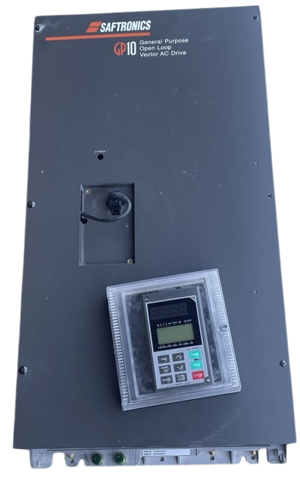
Saftronics Holdings Vector AC Drive GP10E1ST32010
Need answers fast?
Explore the manual using AI.

Turn manuals into instant answers
with your AI-powered assistantTurn manuals into instant answers
with your AI-powered assistant
Manual for Saftronics Holdings Vector AC Drive GP10E1ST32010
Complete asset maintenance, one click away
Get instant access to all the maintenance information you need. Empower technicians to perform preventive maintenance with asset packages, ready to use right out of the box.

Documents & Manuals
Find all the essential guides in one place.
 Tensioning Guide
- Belt-diagram
- C-120 pulleys
+ 13 more

Work Order Templates
Pre-built workflows to keep your asset running smoothly.
- Daily Electrical System Inspection
- Replace Roller and Pulley
- Install Engine B-120
+ 29 more

Procedures
Integrate maintenance plans directly into your work orders.
- Motion Industries
- Applied Industrial Technologies
- Electrical Brothers
+ 5 more

Parts
Access the parts list for your equipment in MaintainX.
- Drive Motor
- B2 Rollers
- Tensioning System
+ 40 more
Saftronics Holdings Vector AC Drive GP10E1ST32010
Create an account to install this asset package.
Maintenance Plans for Saftronics Holdings Vector AC Drive Model GP10E1ST32010
Integrate maintenance plans directly into your work orders in MaintainX.
Main Circuit Capacitors Capacitance Determination
This drive is equipped with a function to automatically indicate the capacitance of the capacitors installed in the main circuit when powering up the drive after disconnecting the power according to the prescribed conditions.
The initial capacitance values are set in the drive when shipped from the factory, and the decrease ratio (%) to those values can be displayed.
Use this function as follows:
(1) Remove any option boards from the inverter. Disconnect the DC bus connections to the main circuit [Terminals P(+) and N(-)] from the braking unit or other inverters, if connected. The power factor correcting reactor (DC reactor) does not need be disconnected. A power supply introduced to the auxiliary input [Terminals R0, T0] that provides control power should be isolated.
(2) Disable all the digital inputs (FWD, REV, X1-X9) on the control terminals. Also disconnect RS485 serial communication, if used. Turn on the main power supply. Confirm that the cooling fan is rotating and that the inverter is not operating. (There is no problem if the “OH2 External thermal relay tripped” function is activated by the digital input terminal.)
(3) Turn the main power off.
(4) Turn on the main power again after verifying that the charge lamp is completely off.
(5) Open the maintenance information on the keypad panel and confirm the capacitance values of the built-in capacitors.;

Periodic Vector AC Drive Inspection
8.2 Periodic Inspections
Periodic inspections should be made after stopping operations, cutting off the power source, and removing the surface cover.
Note that after turning off the power, the smoothing capacitors in the DC section of the main circuit take time to discharge. To prevent electric shock, confirm with a multimeter that the voltage has dropped below the safety value (25 V DC or below) after the charge lamp(CRG) goes off.
WARNING
• Start the inspection at least five minutes after turning off the power supply for inverters rated at 30 Hp or less. Wait at least ten minutes for inverters rated at 40 Hp or more. Check that the charge lamp (CRG) went off and that the voltage is 25V DC or less between terminals P(+) and N(-). Electric shock may result.
• Only authorized personnel should perform maintenance and component replacement operations. Remove metal jewelry such as watches and rings, and always use insulated tools.
• Never modify the drive. Electric shock or injury may result.
Area to Check
Environment
Vector AC Drive Insulation Test
Avoid megger testing on an drive since an insulation test was completed at the factory. If a megger test must be completed, proceed as described below. Incorrect testing methods may result in product damage.
If the specifications for the dielectric strength test are not followed, the drive may be damaged. If a dielectric strength test must be completed, contact your local distributor or nearest Fuji Electric sales office.
(1) Megger test for the main circuit
1. Use a 500V DC megger and isolate the main power before starting measurement.
2. If the test voltage is connected to the control circuit, remove all connection cables to the control circuit.
3. Connect the main circuit terminals using common cables, as shown in Fig. 8-4-1.
4. Perform the megger test only between the common cables connected to the main circuit and ground (Terminal ).
5. A megger indicating 5M Ohm or more is normal. (This is the value measured with only the drive connected.)
(2) Insulation test in the control circuit
1 Daily Vector AC Drive Inspection
The performance, according to standard specifications, is as expected.
The environment conforms to standard specifications.
The keypad panel display is normal.
There are no abnormal sounds, vibrations, or odors.
There are no indications of overheating or discoloration.
Sign off on the daily inspection
Parts for Saftronics Holdings Vector AC Drive GP10E1ST32010
Access the parts list for your equipment in MaintainX.
Main Control Card
SG11CPCBB1
Gate Driver & Power Supply Card
SG11PPCBG2055
Keypad Panel NEMA Type 1
STPAG11S
Capacitor Unit 2700μFx1
SG11CAP09
Fan
SG11FAN202
Main Control Card
SG11CPCBB1
Gate Driver & Power Supply Card
SG11PPCBG2055
Keypad Panel NEMA Type 1
STPAG11S
Capacitor Unit 2700μFx1
SG11CAP09
Fan
SG11FAN202
Main Control Card
SG11CPCBB1
Gate Driver & Power Supply Card
SG11PPCBG2055
Keypad Panel NEMA Type 1
STPAG11S
Capacitor Unit 2700μFx1
SG11CAP09
Fan
SG11FAN202
Unlock efficiency
with MaintainX CoPilot
MaintainX CoPilot is your expert colleague, on call 24/7, helping your team find the answers they need to keep equipment running.
Reduce Unplanned Downtime
Ensure your team follows consistent procedures to minimize equipment failures and costly delays.
Maximize Asset Availability
Keep your assets running longer and more reliably, with standardized maintenance workflows from OEM manuals.
Lower Maintenance Costs
Turn any technician into an expert to streamline operations, maintain more assets, and reduce overall costs.
Thousands of companies manage their assets with MaintainX

'%3e%3cpath%20fill='url(%23b)'%20d='M66.008%2080.068c-5.084-.786-9.763-3.834-12.442-8.68a16.942%2016.942%200%200%201-1.87-5.18c1.096.19%202.203.476%203.298.87%206.525%202.333%2010.836%207.68%2011.014%2012.99ZM51.47%2061.576c.488-5.524%203.62-10.716%208.847-13.597a17.132%2017.132%200%200%201%2011.335-1.882c-.798%208.145-7.43%2014.848-16.038%2015.599-1.417.119-2.799.07-4.144-.12Zm28.564-11.478a17.513%2017.513%200%200%201%203.727%204.62c4.608%208.335%201.584%2018.813-6.75%2023.409a16.988%2016.988%200%200%201-4.359%201.679%2019.624%2019.624%200%200%201-3.977-12.776c.346-7.561%204.942-13.931%2011.36-16.932Z'/%3e%3cpath%20fill='%23110F0D'%20fill-rule='evenodd'%20d='M142.831%2048.324h4.977V77.03h-4.977V48.324Zm27.278%2013.002c.322%201.048.453%202.263.453%203.62v12.073h-4.787V66.208c0-.75-.047-1.572-.154-2.143-.453-2.382-1.822-3.572-4.215-3.572-2.31%200-3.882%201.274-4.43%203.476-.143.596-.226%201.405-.226%202.25v10.8h-4.787V56.623h4.477v2.989c1.536-2.5%203.906-3.43%206.371-3.43%203.488%200%206.263%201.68%207.298%205.144Zm24.636%207.323c0%203.882-2.358%206.525-5.763%207.727-1.298.453-2.632.643-4.62.643h-10.169V48.324h9.085c1.691%200%203.156.143%204.049.38%203.465.93%205.727%203.68%205.727%207.335%200%202.441-.81%204.156-2.762%205.644%202.905%201.417%204.453%203.727%204.453%206.966Zm-15.634-8.656h4.584c1.024%200%201.917-.143%202.536-.417%201.215-.548%201.905-1.608%201.905-3.167%200-1.548-.643-2.572-1.845-3.132-.691-.31-1.762-.452-2.763-.452h-4.417v7.168Zm10.716%208.465c0-1.536-.893-3.37-3.227-3.893-.428-.095-1.036-.143-1.571-.143h-5.918v8.085h5.501c.56%200%201.429-.048%201.953-.167%201.94-.453%203.262-1.846%203.262-3.882Zm47.747-11.847-8.097%2020.408h-4.429l-8.109-20.408h5.191l5.192%2014.574%205.108-14.574h5.144Zm-20.218%2010.002c0%20.69-.036%201.262-.155%201.94h-15.943c.631%202.87%202.714%204.728%205.882%204.728%202.131%200%203.607-.882%204.703-2.525h4.87c-1.762%204.144-5.204%206.692-9.657%206.692-6.084%200-10.537-4.858-10.537-10.49%200-6.108%204.524-10.776%2010.335-10.776%206.239%200%2010.442%204.954%2010.502%2010.43Zm-4.763-1.405c-.333-2.846-2.643-4.858-5.691-4.858-2.894%200-5.287%201.929-5.621%204.858h11.312Zm-72.667%203.44c0%204.787-3.287%208.371-9.419%208.371H119.363V64.66c-1.917.274-3.87.69-5.811%201.238l4.537%2011.121h-5.418l-3.596-9.585c-5.144%202.084-10.085%205.216-14.217%209.585h-4.786L101.8%2048.312h4.56l5.68%2013.883a44.112%2044.112%200%200%201%207.323-1.774V48.312h9.084c1.703%200%203.156.143%204.061.393%203.453.929%205.727%203.667%205.727%207.323%200%201.917-.738%204.179-2.81%205.691%203.06%201.56%204.501%204.025%204.501%206.93Zm-15.634-8.667a62.664%2062.664%200%200%201%202.06-.036c1.703.012%203.239.131%204.608.37%201.441-.549%202.357-1.727%202.357-3.537%200-1.941-.881-3.144-2.488-3.667-.548-.18-1.358-.286-2.322-.286h-4.215v7.156Zm-16.55%203.905-3.715-9.894-6.394%2016.502c2.833-2.595%206.263-4.858%2010.109-6.608Zm27.254%204.74c0-2.775-3.131-4.347-8.513-4.418-.715%200-1.441.011-2.191.047v8.252h5.918c2.548%200%204.786-1.37%204.786-3.882Z'%20clip-rule='evenodd'/%3e%3c/g%3e%3cdefs%3e%3clinearGradient%20id='b'%20x1='51.47'%20x2='85.916'%20y1='62.946'%20y2='62.946'%20gradientUnits='userSpaceOnUse'%3e%3cstop%20stop-color='%23CD9F28'/%3e%3cstop%20offset='1'%20stop-color='%23ECD80B'/%3e%3c/linearGradient%3e%3cclipPath%20id='a'%3e%3cpath%20fill='%23fff'%20d='M51.47%2045.728h186.104V80.14H51.47z'/%3e%3c/clipPath%3e%3c/defs%3e%3c/svg%3e)


More from Saftronics Holdings


Explore Other Assets


© 2026 MaintainX. All rights reserved.