


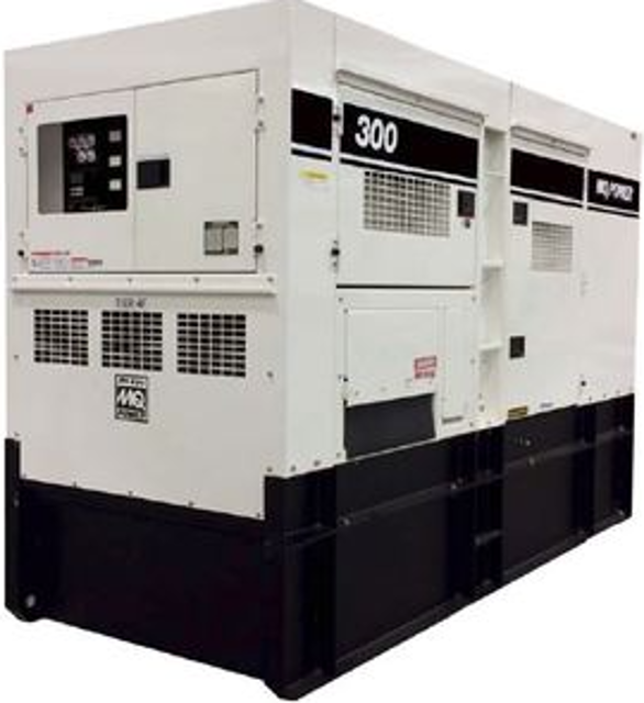
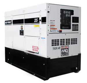
Multiquip Portable Generator DCA300SSJU4F3/PB/PD
Need answers fast?
Explore the manual using AI.
Turn manuals into instant answers
with your AI-powered assistantTurn manuals into instant answers
with your AI-powered assistant
Manual for Multiquip Portable Generator DCA300SSJU4F3/PB/PD
Complete asset maintenance, one click away
Get instant access to all the maintenance information you need. Empower technicians to perform preventive maintenance with asset packages, ready to use right out of the box.

Documents & Manuals
Find all the essential guides in one place.
 Tensioning Guide
- Belt-diagram
- C-120 pulleys
+ 13 more

Work Order Templates
Pre-built workflows to keep your asset running smoothly.
- Daily Electrical System Inspection
- Replace Roller and Pulley
- Install Engine B-120
+ 29 more

Procedures
Integrate maintenance plans directly into your work orders.
- Motion Industries
- Applied Industrial Technologies
- Electrical Brothers
+ 5 more

Parts
Access the parts list for your equipment in MaintainX.
- Drive Motor
- B2 Rollers
- Tensioning System
+ 40 more
Multiquip Portable Generator DCA300SSJU4F3/PB/PD
Create an account to install this asset package.
Maintenance Plans for Multiquip Portable Generator Model DCA300SSJU4F3/PB/PD
Integrate maintenance plans directly into your work orders in MaintainX.
Manual Excitation Test
3-PHASE VOLTAGE TEST
Engine OFF and voltage selector switch in the 3-Phase, 240/139V position
6-pin plug unplugged from the CN1 receptacle on the AVR
SPST toggle switch connected between the positive battery terminal and pin J on the 6-pin plug
Wire connected from the negative battery terminal to pin K on the 6-pin plug
Toggle switch in the OFF (open) position, engine speed switch set to the low position (idle)
Engine started and toggle switch placed in ON position (closed)
Engine speed switch placed in the high position and engine running at full rpm
Selection dial on the multimeter placed to the AC volts position

Electrical Inspection
Warning: This inspection requires trained personnel with PPE!
Visual inspection of generator for environmental factors
Inspection of electrical connections for rust, corrosion, and oxidation
Check for carbon flash deposits around the 120/240V AC receptacles
Signs of wire overheating (discoloration and a burnt smell)
Check for infestation inside the generator
Check for loose hardware
Check terminal lugs/bus bars for secure tightening
Check electrical connectors for good connection
Relay Base Holder Maintenance
Warning: This procedure requires trained personnel with PPE!
Fuel pump relay tested normal?
If fuel pump relay did not test normal, report the issue to the maintenance team and stop the procedure
Is the generator model between DCA6 and DCA125?
If the generator model is not between DCA6 and DCA125, report the issue to the maintenance team and stop the procedure
Is the relay base holder not a ‘sealed type’?
If the relay base holder is a ‘sealed type’, report the issue to the maintenance team and stop the procedure
Is there corrosion and dirt in the relay base holder?
If there is no corrosion and dirt in the relay base holder, report the issue to the maintenance team and stop the procedure
Ocr Test
Warning: Only perform this test with no load on the generator.
Place the selection dial on the multimeter to the W position, then select the sound icon.
With the engine OFF and no power applied to the relay, place the multimeter leads across terminals 95 and 96 on the relay and verify that there is continuity. This implies a CLOSED circuit, continuity.
PRESS the spring-loaded relay reset button.
Move the multimeter leads to terminals 97 and 98 on the relay and verify that there is no continuity. This implies an OPEN circuit, no continuity.
To trip the OCR, slide the manual trip lever on the relay and verify that the multimeter indicates an OPEN circuit across terminals 95 and 96. This implies an OPEN circuit, no continuity.
Move the multimeter leads to terminals 97 and 98 on the relay and verify that there is continuity. This implies a CLOSED circuit, continuity.
Sign off on the OCR test
Surge Protector Check
NOTICE: Before performing the continuity check, both surge protector lead wires (Figure 50) must be disconnected from the rotating rectifier.
Surge protector lead wires disconnected from the rotating rectifier
Place the selection dial on the multimeter in the Ω position.
Selection dial on the multimeter in the Ω position
Next, place the multimeter leads across the surge protector as shown in Figure 50 and verify that the meter displays an open circuit.
Multimeter leads placed across the surge protector
Meter displays an open circuit
If the meter indicates continuity or another reading, replace the surge protector.
Does the meter indicate continuity or another reading?
Parts for Multiquip Portable Generator DCA300SSJU4F3/PB/PD
Access the parts list for your equipment in MaintainX.
Output Terminal Bolt
M9220100914
Tie Bolt 123.0 N.M
M9220101004
Change-Over Board Bolt
M9220101104
Output Terminal Bolt
M9220100914
Tie Bolt 123.0 N.M
M9220101004
Change-Over Board Bolt
M9220101104
Output Terminal Bolt
M9220100914
Tie Bolt 123.0 N.M
M9220101004
Change-Over Board Bolt
M9220101104
Unlock efficiency
with MaintainX CoPilot
MaintainX CoPilot is your expert colleague, on call 24/7, helping your team find the answers they need to keep equipment running.
Reduce Unplanned Downtime
Ensure your team follows consistent procedures to minimize equipment failures and costly delays.
Maximize Asset Availability
Keep your assets running longer and more reliably, with standardized maintenance workflows from OEM manuals.
Lower Maintenance Costs
Turn any technician into an expert to streamline operations, maintain more assets, and reduce overall costs.
Thousands of companies manage their assets with MaintainX

'%3e%3cpath%20fill='url(%23b)'%20d='M66.008%2080.068c-5.084-.786-9.763-3.834-12.442-8.68a16.942%2016.942%200%200%201-1.87-5.18c1.096.19%202.203.476%203.298.87%206.525%202.333%2010.836%207.68%2011.014%2012.99ZM51.47%2061.576c.488-5.524%203.62-10.716%208.847-13.597a17.132%2017.132%200%200%201%2011.335-1.882c-.798%208.145-7.43%2014.848-16.038%2015.599-1.417.119-2.799.07-4.144-.12Zm28.564-11.478a17.513%2017.513%200%200%201%203.727%204.62c4.608%208.335%201.584%2018.813-6.75%2023.409a16.988%2016.988%200%200%201-4.359%201.679%2019.624%2019.624%200%200%201-3.977-12.776c.346-7.561%204.942-13.931%2011.36-16.932Z'/%3e%3cpath%20fill='%23110F0D'%20fill-rule='evenodd'%20d='M142.831%2048.324h4.977V77.03h-4.977V48.324Zm27.278%2013.002c.322%201.048.453%202.263.453%203.62v12.073h-4.787V66.208c0-.75-.047-1.572-.154-2.143-.453-2.382-1.822-3.572-4.215-3.572-2.31%200-3.882%201.274-4.43%203.476-.143.596-.226%201.405-.226%202.25v10.8h-4.787V56.623h4.477v2.989c1.536-2.5%203.906-3.43%206.371-3.43%203.488%200%206.263%201.68%207.298%205.144Zm24.636%207.323c0%203.882-2.358%206.525-5.763%207.727-1.298.453-2.632.643-4.62.643h-10.169V48.324h9.085c1.691%200%203.156.143%204.049.38%203.465.93%205.727%203.68%205.727%207.335%200%202.441-.81%204.156-2.762%205.644%202.905%201.417%204.453%203.727%204.453%206.966Zm-15.634-8.656h4.584c1.024%200%201.917-.143%202.536-.417%201.215-.548%201.905-1.608%201.905-3.167%200-1.548-.643-2.572-1.845-3.132-.691-.31-1.762-.452-2.763-.452h-4.417v7.168Zm10.716%208.465c0-1.536-.893-3.37-3.227-3.893-.428-.095-1.036-.143-1.571-.143h-5.918v8.085h5.501c.56%200%201.429-.048%201.953-.167%201.94-.453%203.262-1.846%203.262-3.882Zm47.747-11.847-8.097%2020.408h-4.429l-8.109-20.408h5.191l5.192%2014.574%205.108-14.574h5.144Zm-20.218%2010.002c0%20.69-.036%201.262-.155%201.94h-15.943c.631%202.87%202.714%204.728%205.882%204.728%202.131%200%203.607-.882%204.703-2.525h4.87c-1.762%204.144-5.204%206.692-9.657%206.692-6.084%200-10.537-4.858-10.537-10.49%200-6.108%204.524-10.776%2010.335-10.776%206.239%200%2010.442%204.954%2010.502%2010.43Zm-4.763-1.405c-.333-2.846-2.643-4.858-5.691-4.858-2.894%200-5.287%201.929-5.621%204.858h11.312Zm-72.667%203.44c0%204.787-3.287%208.371-9.419%208.371H119.363V64.66c-1.917.274-3.87.69-5.811%201.238l4.537%2011.121h-5.418l-3.596-9.585c-5.144%202.084-10.085%205.216-14.217%209.585h-4.786L101.8%2048.312h4.56l5.68%2013.883a44.112%2044.112%200%200%201%207.323-1.774V48.312h9.084c1.703%200%203.156.143%204.061.393%203.453.929%205.727%203.667%205.727%207.323%200%201.917-.738%204.179-2.81%205.691%203.06%201.56%204.501%204.025%204.501%206.93Zm-15.634-8.667a62.664%2062.664%200%200%201%202.06-.036c1.703.012%203.239.131%204.608.37%201.441-.549%202.357-1.727%202.357-3.537%200-1.941-.881-3.144-2.488-3.667-.548-.18-1.358-.286-2.322-.286h-4.215v7.156Zm-16.55%203.905-3.715-9.894-6.394%2016.502c2.833-2.595%206.263-4.858%2010.109-6.608Zm27.254%204.74c0-2.775-3.131-4.347-8.513-4.418-.715%200-1.441.011-2.191.047v8.252h5.918c2.548%200%204.786-1.37%204.786-3.882Z'%20clip-rule='evenodd'/%3e%3c/g%3e%3cdefs%3e%3clinearGradient%20id='b'%20x1='51.47'%20x2='85.916'%20y1='62.946'%20y2='62.946'%20gradientUnits='userSpaceOnUse'%3e%3cstop%20stop-color='%23CD9F28'/%3e%3cstop%20offset='1'%20stop-color='%23ECD80B'/%3e%3c/linearGradient%3e%3cclipPath%20id='a'%3e%3cpath%20fill='%23fff'%20d='M51.47%2045.728h186.104V80.14H51.47z'/%3e%3c/clipPath%3e%3c/defs%3e%3c/svg%3e)


More from Multiquip


Explore Other Assets


© 2026 MaintainX. All rights reserved.