


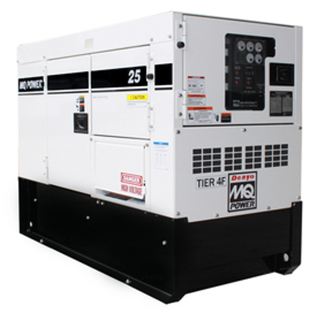
Multiquip Portable Generator DCA25SSIU4F
Need answers fast?
Explore the manual using AI.
Turn manuals into instant answers
with your AI-powered assistantTurn manuals into instant answers
with your AI-powered assistant
Manual for Multiquip Portable Generator DCA25SSIU4F
Complete asset maintenance, one click away
Get instant access to all the maintenance information you need. Empower technicians to perform preventive maintenance with asset packages, ready to use right out of the box.

Documents & Manuals
Find all the essential guides in one place.
 Tensioning Guide
- Belt-diagram
- C-120 pulleys
+ 13 more

Work Order Templates
Pre-built workflows to keep your asset running smoothly.
- Daily Electrical System Inspection
- Replace Roller and Pulley
- Install Engine B-120
+ 29 more

Procedures
Integrate maintenance plans directly into your work orders.
- Motion Industries
- Applied Industrial Technologies
- Electrical Brothers
+ 5 more

Parts
Access the parts list for your equipment in MaintainX.
- Drive Motor
- B2 Rollers
- Tensioning System
+ 40 more
Multiquip Portable Generator DCA25SSIU4F
Create an account to install this asset package.
Maintenance Plans for Multiquip Portable Generator Model DCA25SSIU4F
Integrate maintenance plans directly into your work orders in MaintainX.
Mpu Adjustment
Loosen the jam nut that secures the MPU to the sensor plate
Remove MPU
Visually view the flywheel teeth through the hole opening on the sensor plate
Attach a ratchet to the crankshaft pulley and rotate the flywheel gear until the highest point of the flywheel gear tooth is visible
Reinstall the MPU sensor back into the sensor plate. Continue screwing the MPU sensor clockwise until contact is made with the flywheel gear tooth
After making contact with the flywheel gear tooth, unscrew the MPU sensor counterclockwise 1/2 turn
Verify that the MPU sensor does not make contact with the flywheel by rotating the flywheel gear completely around. Flywheel should rotate freely
The MPU sensor-flywheel gear gap should be adjusted so that the minimum voltage required is attained while the engine is in crank status. The voltage setting we are looking to obtain is 2.25 VAC +/- 0.50 VAC
Once the correct gap is obtained, tighten the MPU sensor jam nut to secure it to the sensor plate

Relay Base Holder Maintenance
Warning: This procedure requires trained personnel with PPE!
Fuel pump relay tested normal?
If fuel pump relay did not test normal, report the issue to the maintenance team and stop the procedure
Upload a photo of the relay base holder before cleaning
Dielectric cleaner sprayed onto the contact pins on the relay base holder?
Enter the air pressure used for blowing off dirt and debris
Dirt and debris removed from the relay base holder contact pins?
Upload a photo of the relay base holder after cleaning
Fuel pump relay reinstalled back into its base holder?
Rheostat Check
NOTICE: Before performing the resistance check, the CN14 connector plug (Figure 53) must be disconnected from the CN4 receptacle on the AVR. If the reading indicates an open circuit or incorrect reading replace the rheostat.
Symptom: AC voltage output is half the normal value and there is no response when adjusting rheostat.
Disconnect the CN14 plug from the CN4 receptacle on the AVR and measure the resistance of the rheostat at the connector plug.
Set the multimeter selection dial to to the W position as shown in Figure 53A.
Place the multimeter leads between pins 1 and 3 on the CN14 connector plug (Figure 53B). Turn the voltage control knob (Figure 53C) fully counterclockwise. The multimeter should read zero ohms (Figure 53D).
Next, turn the knob slowly until the knob is fully clockwise and the multimeter should read about 1000 ohms (Figure 53E).
Sign off on the rheostat check
Fault Delay Adjustment
Warning: Only trained personnel should perform this adjustment
Engine is off and cool?
Turn the engine fault delay adjustment potentiometer (Figure 56E) 30 turns counterclockwise.
Potentiometer turned 30 turns counterclockwise?
This will allow for about 1 second of fault delay. Fault delay is begun after the engine has started.
Engine started and running in fault mode for about 1 second?
The purpose of the delay is to allow time for oil pressure to build adequately, before the oil pressure monitor starts checking the oil pressure sender.
Enter the oil pressure reading
High water temperature is also ignored during the fault delay time to allow engine coolant to circulate in the engine.
Main Armature Avr Inputs Resistance Check
NOTICE: Before performing the resistance check, the 6-pin plug (Figure 51B) must be disconnected from the CN1 receptacle on the AVR. If the reading indicates an open circuit the component may have to be replaced or repaired.
Set the multimeter selection dial to the W position as shown in Figure 51A.
Resistance across the A-B, C-D, D-A open delta wire leads as referenced in Figure 51B.
Resistance across the B-C open delta wire leads as referenced in Figure 51B.
Again, be sure to unplug the 6-pin plug from the CN1 receptacle on the AVR.
As shown in Figure 52 there are three outside connectors that plug into the CN1, CN3 and CN4 receptacles on the AVR.
The CN2 receptacle has no outside plug connected to it. Pins 1 and 2 are internally jumpered together and pins 3 and 4 are also jumpered together.
As shown in Figure 52 there are two WHITE wires that connect to the AVR 2-pin terminal block via relay unit RY1.
The AVR also has three potentiometers only one is used for coarse adjustment of the voltage, the other two are factory set and should NOT be adjusted. In addition there is an 8-amp circuit protection fuse.
Parts for Multiquip Portable Generator DCA25SSIU4F
Access the parts list for your equipment in MaintainX.
Output Terminal Bolt
M9220000004B
Tie Bolt 7.4 N.M
M9220000104A
Output Terminal Bolt
M9220000004B
Tie Bolt 7.4 N.M
M9220000104A
Output Terminal Bolt
M9220000004B
Tie Bolt 7.4 N.M
M9220000104A
Unlock efficiency
with MaintainX CoPilot
MaintainX CoPilot is your expert colleague, on call 24/7, helping your team find the answers they need to keep equipment running.
Reduce Unplanned Downtime
Ensure your team follows consistent procedures to minimize equipment failures and costly delays.
Maximize Asset Availability
Keep your assets running longer and more reliably, with standardized maintenance workflows from OEM manuals.
Lower Maintenance Costs
Turn any technician into an expert to streamline operations, maintain more assets, and reduce overall costs.
Thousands of companies manage their assets with MaintainX

'%3e%3cpath%20fill='url(%23b)'%20d='M66.008%2080.068c-5.084-.786-9.763-3.834-12.442-8.68a16.942%2016.942%200%200%201-1.87-5.18c1.096.19%202.203.476%203.298.87%206.525%202.333%2010.836%207.68%2011.014%2012.99ZM51.47%2061.576c.488-5.524%203.62-10.716%208.847-13.597a17.132%2017.132%200%200%201%2011.335-1.882c-.798%208.145-7.43%2014.848-16.038%2015.599-1.417.119-2.799.07-4.144-.12Zm28.564-11.478a17.513%2017.513%200%200%201%203.727%204.62c4.608%208.335%201.584%2018.813-6.75%2023.409a16.988%2016.988%200%200%201-4.359%201.679%2019.624%2019.624%200%200%201-3.977-12.776c.346-7.561%204.942-13.931%2011.36-16.932Z'/%3e%3cpath%20fill='%23110F0D'%20fill-rule='evenodd'%20d='M142.831%2048.324h4.977V77.03h-4.977V48.324Zm27.278%2013.002c.322%201.048.453%202.263.453%203.62v12.073h-4.787V66.208c0-.75-.047-1.572-.154-2.143-.453-2.382-1.822-3.572-4.215-3.572-2.31%200-3.882%201.274-4.43%203.476-.143.596-.226%201.405-.226%202.25v10.8h-4.787V56.623h4.477v2.989c1.536-2.5%203.906-3.43%206.371-3.43%203.488%200%206.263%201.68%207.298%205.144Zm24.636%207.323c0%203.882-2.358%206.525-5.763%207.727-1.298.453-2.632.643-4.62.643h-10.169V48.324h9.085c1.691%200%203.156.143%204.049.38%203.465.93%205.727%203.68%205.727%207.335%200%202.441-.81%204.156-2.762%205.644%202.905%201.417%204.453%203.727%204.453%206.966Zm-15.634-8.656h4.584c1.024%200%201.917-.143%202.536-.417%201.215-.548%201.905-1.608%201.905-3.167%200-1.548-.643-2.572-1.845-3.132-.691-.31-1.762-.452-2.763-.452h-4.417v7.168Zm10.716%208.465c0-1.536-.893-3.37-3.227-3.893-.428-.095-1.036-.143-1.571-.143h-5.918v8.085h5.501c.56%200%201.429-.048%201.953-.167%201.94-.453%203.262-1.846%203.262-3.882Zm47.747-11.847-8.097%2020.408h-4.429l-8.109-20.408h5.191l5.192%2014.574%205.108-14.574h5.144Zm-20.218%2010.002c0%20.69-.036%201.262-.155%201.94h-15.943c.631%202.87%202.714%204.728%205.882%204.728%202.131%200%203.607-.882%204.703-2.525h4.87c-1.762%204.144-5.204%206.692-9.657%206.692-6.084%200-10.537-4.858-10.537-10.49%200-6.108%204.524-10.776%2010.335-10.776%206.239%200%2010.442%204.954%2010.502%2010.43Zm-4.763-1.405c-.333-2.846-2.643-4.858-5.691-4.858-2.894%200-5.287%201.929-5.621%204.858h11.312Zm-72.667%203.44c0%204.787-3.287%208.371-9.419%208.371H119.363V64.66c-1.917.274-3.87.69-5.811%201.238l4.537%2011.121h-5.418l-3.596-9.585c-5.144%202.084-10.085%205.216-14.217%209.585h-4.786L101.8%2048.312h4.56l5.68%2013.883a44.112%2044.112%200%200%201%207.323-1.774V48.312h9.084c1.703%200%203.156.143%204.061.393%203.453.929%205.727%203.667%205.727%207.323%200%201.917-.738%204.179-2.81%205.691%203.06%201.56%204.501%204.025%204.501%206.93Zm-15.634-8.667a62.664%2062.664%200%200%201%202.06-.036c1.703.012%203.239.131%204.608.37%201.441-.549%202.357-1.727%202.357-3.537%200-1.941-.881-3.144-2.488-3.667-.548-.18-1.358-.286-2.322-.286h-4.215v7.156Zm-16.55%203.905-3.715-9.894-6.394%2016.502c2.833-2.595%206.263-4.858%2010.109-6.608Zm27.254%204.74c0-2.775-3.131-4.347-8.513-4.418-.715%200-1.441.011-2.191.047v8.252h5.918c2.548%200%204.786-1.37%204.786-3.882Z'%20clip-rule='evenodd'/%3e%3c/g%3e%3cdefs%3e%3clinearGradient%20id='b'%20x1='51.47'%20x2='85.916'%20y1='62.946'%20y2='62.946'%20gradientUnits='userSpaceOnUse'%3e%3cstop%20stop-color='%23CD9F28'/%3e%3cstop%20offset='1'%20stop-color='%23ECD80B'/%3e%3c/linearGradient%3e%3cclipPath%20id='a'%3e%3cpath%20fill='%23fff'%20d='M51.47%2045.728h186.104V80.14H51.47z'/%3e%3c/clipPath%3e%3c/defs%3e%3c/svg%3e)


More from Multiquip


Explore Other Assets


© 2026 MaintainX. All rights reserved.