


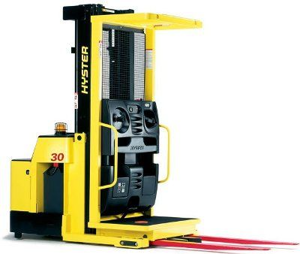
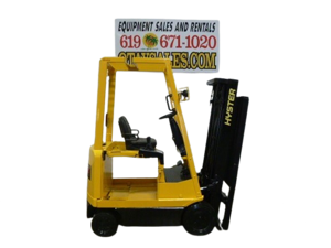
Hyster-Yale Lift Truck GLP060VXNDAE087
Need answers fast?
Explore the manual using AI.
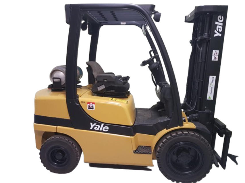
The Hyster-Yale Lift Truck GLP060VXNDAE087 is a robust internal combustion forklift designed for efficient material handling in industrial environments. Known for its reliability and performance, this model excels in maneuverability and lifting capabilities, making it ideal for various warehouse and construction applications.
Turn manuals into instant answers
with your AI-powered assistantTurn manuals into instant answers
with your AI-powered assistant
Manual for Hyster-Yale Lift Truck GLP060VXNDAE087
Complete asset maintenance, one click away
Get instant access to all the maintenance information you need. Empower technicians to perform preventive maintenance with asset packages, ready to use right out of the box.

Documents & Manuals
Find all the essential guides in one place.
 Tensioning Guide
- Belt-diagram
- C-120 pulleys
+ 13 more

Work Order Templates
Pre-built workflows to keep your asset running smoothly.
- Daily Electrical System Inspection
- Replace Roller and Pulley
- Install Engine B-120
+ 29 more

Procedures
Integrate maintenance plans directly into your work orders.
- Motion Industries
- Applied Industrial Technologies
- Electrical Brothers
+ 5 more

Parts
Access the parts list for your equipment in MaintainX.
- Drive Motor
- B2 Rollers
- Tensioning System
+ 40 more
Hyster-Yale Lift Truck GLP060VXNDAE087
Create an account to install this asset package.
Maintenance Plans for Hyster-Yale Lift Truck Model GLP060VXNDAE087
Integrate maintenance plans directly into your work orders in MaintainX.
Hood, Seat and Side Cover Replacement
REMOVAL
Slide seat to the closest position to steering column
Fully tilt steering column forward
It your truck is equipped with an LPG tank, swing tank off to the side
Raise latch on the left, front corner of the hood to unlatch and lift up hood
Remove floor mat and floor plate
Remove two capscrews holding left and right rear side covers to the frame. Remove rear side covers from frame
Remove two capscrews holding left and right fender covers to front overhead guard leg. Remove covers
Remove four capscrews holding left and right front side covers to frame. Remove covers

Engine Replacement
WARNING! LPG can cause an explosion. DO NOT cause sparks or permit flammable material near the LPG system.
LPG fuel systems disconnected indoors?
Overhead guard removed?
Floor mat and floor plate removed?
WARNING! DO NOT remove the radiator cap from the radiator when the engine is hot.
Coolant cooled to ambient temperature?
Drain pan placed under radiator?
Radiator cap removed?
Coolant drained from radiator and engine?
Counterweight Replacement
REMOVAL
If the lift truck has an LPG fuel system, see one of the following Service Manuals to remove the LPG tank and bracket, before removing the coun terweight, and for additional information on the LPG fuel systems
Install a lifting eye in the lift hole of the counter-weight. Connect a crane to the lifting eye and raise the crane until it holds part of the weight of the counterweight. Remove the tow pin and remove the capscrew that holds the counterweight to the frame. Use the crane to lift the counterweight from the lift truck. Put counterweight on the floor so that it has stability and will not fall over. Take care not to damage exhaust or cooling components
INSTALLATION
Make sure the seals are on the counterweight
Use a crane to install the counterweight on the lift truck. When the counterweight is installed, make sure the hooks on the frame fully engage the coun terweight so it is aligned with the parts of the frame. Install and tighten the M24 x 3 capscrew to 555 Nem (409 Ibf ft)
Install tow pin and roll pin. See Tow Pin, Remove and Install for procedures
If lift truck is equipped with an overhead exhaust system, install the overhead exhaust pipe. See the section Exhaust System Repair for the procedures;
Throttle Pedal and Cable Adjustment
NOTE: There are no throttle pedal and cable adjustments for lift trucks equipped with the GM 2.4L engine. The GM 2.4L engines have an electronic throttle that is self-adjusting and self-calibrating
NOTE: For the Mazda 2007 emission compliant engines and for lift trucks built after January, 2010 and equipped with a Mazda engine, there is only a throttle pedal stop adjustment. The engine has an electronic throttle that is self-adjusting and self calibrating
Remove floor plate and disconnect throttle cable from the bellcrank and engine
Fully depress throttle pedal and verify that the dimension between the bellcrank and cowl plate is 6≤2 mm (0.24 ≤0.08 in.)
If dimension is not correct, adjust ball ends on push rod so that a minimum of 6 mm (0.24 in.) of threaded rod screws into each ball end
Connect throttle cable to bellcrank and engine
With throttle pedal in full up position, adjust throttle cable, using the jam nuts (item #10 in Figure 38) to remove all slack from the cable. Cable should be adjusted to the point where additional adjustment will pull the throttle crank off the idle stop. Tighten jam nuts to 8 to 15 Nem (71 to 133 ibf in)
NOTE: Il lift truck is equipped with a Electronic Control Transmission, see the section Calibration Procedures 8000 YRM 1134 for additional adjustment procedures before going onto Step 7
Fully depress pedal and verify that full pedal stroke brings the throttle crank to within 3.0 mm (0.12 in.) of the wide open throttle stop
Steering Column Inspection
Inspect for loose, burned, missing, cracked or damaged hardware
Inspect all parts for dents, holes, bends, burrs, rust, corrosion or marred finishes
Replace all defective or damaged parts
Sign off on the steering column inspection
Parts for Hyster-Yale Lift Truck GLP060VXNDAE087
Access the parts list for your equipment in MaintainX.
Operator's Cab
524306203
Frame
524223754
Electrical System
524223772
Drive Axle Wet Brake
524240908
Calibration Procedures
524223780
Operator's Cab
524306203
Frame
524223754
Electrical System
524223772
Drive Axle Wet Brake
524240908
Calibration Procedures
524223780
Operator's Cab
524306203
Frame
524223754
Electrical System
524223772
Drive Axle Wet Brake
524240908
Calibration Procedures
524223780
Unlock efficiency
with MaintainX CoPilot
MaintainX CoPilot is your expert colleague, on call 24/7, helping your team find the answers they need to keep equipment running.
Reduce Unplanned Downtime
Ensure your team follows consistent procedures to minimize equipment failures and costly delays.
Maximize Asset Availability
Keep your assets running longer and more reliably, with standardized maintenance workflows from OEM manuals.
Lower Maintenance Costs
Turn any technician into an expert to streamline operations, maintain more assets, and reduce overall costs.
Thousands of companies manage their assets with MaintainX

'%3e%3cpath%20fill='url(%23b)'%20d='M66.008%2080.068c-5.084-.786-9.763-3.834-12.442-8.68a16.942%2016.942%200%200%201-1.87-5.18c1.096.19%202.203.476%203.298.87%206.525%202.333%2010.836%207.68%2011.014%2012.99ZM51.47%2061.576c.488-5.524%203.62-10.716%208.847-13.597a17.132%2017.132%200%200%201%2011.335-1.882c-.798%208.145-7.43%2014.848-16.038%2015.599-1.417.119-2.799.07-4.144-.12Zm28.564-11.478a17.513%2017.513%200%200%201%203.727%204.62c4.608%208.335%201.584%2018.813-6.75%2023.409a16.988%2016.988%200%200%201-4.359%201.679%2019.624%2019.624%200%200%201-3.977-12.776c.346-7.561%204.942-13.931%2011.36-16.932Z'/%3e%3cpath%20fill='%23110F0D'%20fill-rule='evenodd'%20d='M142.831%2048.324h4.977V77.03h-4.977V48.324Zm27.278%2013.002c.322%201.048.453%202.263.453%203.62v12.073h-4.787V66.208c0-.75-.047-1.572-.154-2.143-.453-2.382-1.822-3.572-4.215-3.572-2.31%200-3.882%201.274-4.43%203.476-.143.596-.226%201.405-.226%202.25v10.8h-4.787V56.623h4.477v2.989c1.536-2.5%203.906-3.43%206.371-3.43%203.488%200%206.263%201.68%207.298%205.144Zm24.636%207.323c0%203.882-2.358%206.525-5.763%207.727-1.298.453-2.632.643-4.62.643h-10.169V48.324h9.085c1.691%200%203.156.143%204.049.38%203.465.93%205.727%203.68%205.727%207.335%200%202.441-.81%204.156-2.762%205.644%202.905%201.417%204.453%203.727%204.453%206.966Zm-15.634-8.656h4.584c1.024%200%201.917-.143%202.536-.417%201.215-.548%201.905-1.608%201.905-3.167%200-1.548-.643-2.572-1.845-3.132-.691-.31-1.762-.452-2.763-.452h-4.417v7.168Zm10.716%208.465c0-1.536-.893-3.37-3.227-3.893-.428-.095-1.036-.143-1.571-.143h-5.918v8.085h5.501c.56%200%201.429-.048%201.953-.167%201.94-.453%203.262-1.846%203.262-3.882Zm47.747-11.847-8.097%2020.408h-4.429l-8.109-20.408h5.191l5.192%2014.574%205.108-14.574h5.144Zm-20.218%2010.002c0%20.69-.036%201.262-.155%201.94h-15.943c.631%202.87%202.714%204.728%205.882%204.728%202.131%200%203.607-.882%204.703-2.525h4.87c-1.762%204.144-5.204%206.692-9.657%206.692-6.084%200-10.537-4.858-10.537-10.49%200-6.108%204.524-10.776%2010.335-10.776%206.239%200%2010.442%204.954%2010.502%2010.43Zm-4.763-1.405c-.333-2.846-2.643-4.858-5.691-4.858-2.894%200-5.287%201.929-5.621%204.858h11.312Zm-72.667%203.44c0%204.787-3.287%208.371-9.419%208.371H119.363V64.66c-1.917.274-3.87.69-5.811%201.238l4.537%2011.121h-5.418l-3.596-9.585c-5.144%202.084-10.085%205.216-14.217%209.585h-4.786L101.8%2048.312h4.56l5.68%2013.883a44.112%2044.112%200%200%201%207.323-1.774V48.312h9.084c1.703%200%203.156.143%204.061.393%203.453.929%205.727%203.667%205.727%207.323%200%201.917-.738%204.179-2.81%205.691%203.06%201.56%204.501%204.025%204.501%206.93Zm-15.634-8.667a62.664%2062.664%200%200%201%202.06-.036c1.703.012%203.239.131%204.608.37%201.441-.549%202.357-1.727%202.357-3.537%200-1.941-.881-3.144-2.488-3.667-.548-.18-1.358-.286-2.322-.286h-4.215v7.156Zm-16.55%203.905-3.715-9.894-6.394%2016.502c2.833-2.595%206.263-4.858%2010.109-6.608Zm27.254%204.74c0-2.775-3.131-4.347-8.513-4.418-.715%200-1.441.011-2.191.047v8.252h5.918c2.548%200%204.786-1.37%204.786-3.882Z'%20clip-rule='evenodd'/%3e%3c/g%3e%3cdefs%3e%3clinearGradient%20id='b'%20x1='51.47'%20x2='85.916'%20y1='62.946'%20y2='62.946'%20gradientUnits='userSpaceOnUse'%3e%3cstop%20stop-color='%23CD9F28'/%3e%3cstop%20offset='1'%20stop-color='%23ECD80B'/%3e%3c/linearGradient%3e%3cclipPath%20id='a'%3e%3cpath%20fill='%23fff'%20d='M51.47%2045.728h186.104V80.14H51.47z'/%3e%3c/clipPath%3e%3c/defs%3e%3c/svg%3e)


More from Hyster-Yale


Explore Other Assets


© 2026 MaintainX. All rights reserved.