


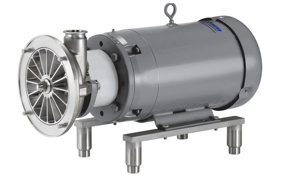
FRISTAM Shear Pump FSPE 3522
Need answers fast?
Explore the manual using AI.

Turn manuals into instant answers
with your AI-powered assistantTurn manuals into instant answers
with your AI-powered assistant
Manual for FRISTAM Shear Pump FSPE 3522
Complete asset maintenance, one click away
Get instant access to all the maintenance information you need. Empower technicians to perform preventive maintenance with asset packages, ready to use right out of the box.

Documents & Manuals
Find all the essential guides in one place.
 Tensioning Guide
- Belt-diagram
- C-120 pulleys
+ 13 more

Work Order Templates
Pre-built workflows to keep your asset running smoothly.
- Daily Electrical System Inspection
- Replace Roller and Pulley
- Install Engine B-120
+ 29 more

Procedures
Integrate maintenance plans directly into your work orders.
- Motion Industries
- Applied Industrial Technologies
- Electrical Brothers
+ 5 more

Parts
Access the parts list for your equipment in MaintainX.
- Drive Motor
- B2 Rollers
- Tensioning System
+ 40 more
FRISTAM Shear Pump FSPE 3522
Create an account to install this asset package.
Maintenance Plans for FRISTAM Shear Pump Model FSPE 3522
Integrate maintenance plans directly into your work orders in MaintainX.
Shaft Seal Replacement
The shaft seal must be replaced if
– Pumping medium or sealing or quenching liquid flows out of the pump on the atmosphere side
– Sealing liquid leaks into the pumping medium
1. Dismantle the pump head. See Chapter 9.8, "Pump Head Removal" page 17
2. Replace the mechanical seal and mount the pump head. See Chapter 9.10, "Pump Head Attachment" page 19. Perform the following tasks according to the given shaft seal
– Preassemble the seals on the shaft
– Preassemble the pump casing
– Mount the pump casing on the lantern
– Mount the mechanical seal

5000 Hourly L2, L3, L4 Models Oil Change
Motor reached normal operating temperature
Motor turned off and secured from accidental turn on
Oil collection container placed under the oil drain plug
Caution! Danger of burning from hot oil. Wear suitable protective gloves.
Oil drain plug loosened and removed
Oil completely drained and disposed of in accordance with local regulations
Oil drain plug and seal cleaned and remounted
Type of oil used
Amount of oil used (refer to Table 4 'Oil volumes')
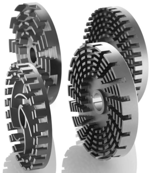
Pump Clearance Check
Impeller–Pump Casing Clearance
Pump cover has been removed
Pump casing is connected firmly to the lantern
The impeller has been mounted and the impeller nut tightened
Measure the clearance Z between the pump casing (47) and the impeller (46) using vernier calipers
Compare the clearance Z with Table 7 'Clearances' page 19
Impeller–Pump Cover Clearance
Pipe on discharge line fitting has been detached
Pump casing is connected firmly to the lantern
Motor Replacement
Turn off the motor and prevent it from being able to be turned on accidentally
Remove the pump head
Take the lantern off of the motor
Remove the shaft
Replace the motor
Mount the shaft and align
Mount the lantern
Only for flange connection: Check the clearance if necessary
Replace the mechanical seal and mount the pump head
5000 Hourly L1 Model Shaft Bearing Lubrication
Warning: This procedure requires trained personnel with PPE!
Cover off of the bearing block
Bearing cap removed on the pump side
Bearing cap removed on the motor side
Shaft forced out in the direction of the pump head
Note: All parts that are gray in the above two figures remain on the shaft
Surfaces of all parts cleaned and checked for damage
Select the type of lubricant used
Pump shaft with the bearing pressed into the bearing block
Parts for FRISTAM Shear Pump FSPE 3522
Access the parts list for your equipment in MaintainX.
Pump Casing
101
Stage Casing
108
Cover
160
Back Casing Panel
13-1
Housing Insert
13-2
Pump Casing
101
Stage Casing
108
Cover
160
Back Casing Panel
13-1
Housing Insert
13-2
Pump Casing
101
Stage Casing
108
Cover
160
Back Casing Panel
13-1
Housing Insert
13-2
Unlock efficiency
with MaintainX CoPilot
MaintainX CoPilot is your expert colleague, on call 24/7, helping your team find the answers they need to keep equipment running.
Reduce Unplanned Downtime
Ensure your team follows consistent procedures to minimize equipment failures and costly delays.
Maximize Asset Availability
Keep your assets running longer and more reliably, with standardized maintenance workflows from OEM manuals.
Lower Maintenance Costs
Turn any technician into an expert to streamline operations, maintain more assets, and reduce overall costs.
Thousands of companies manage their assets with MaintainX

'%3e%3cpath%20fill='url(%23b)'%20d='M66.008%2080.068c-5.084-.786-9.763-3.834-12.442-8.68a16.942%2016.942%200%200%201-1.87-5.18c1.096.19%202.203.476%203.298.87%206.525%202.333%2010.836%207.68%2011.014%2012.99ZM51.47%2061.576c.488-5.524%203.62-10.716%208.847-13.597a17.132%2017.132%200%200%201%2011.335-1.882c-.798%208.145-7.43%2014.848-16.038%2015.599-1.417.119-2.799.07-4.144-.12Zm28.564-11.478a17.513%2017.513%200%200%201%203.727%204.62c4.608%208.335%201.584%2018.813-6.75%2023.409a16.988%2016.988%200%200%201-4.359%201.679%2019.624%2019.624%200%200%201-3.977-12.776c.346-7.561%204.942-13.931%2011.36-16.932Z'/%3e%3cpath%20fill='%23110F0D'%20fill-rule='evenodd'%20d='M142.831%2048.324h4.977V77.03h-4.977V48.324Zm27.278%2013.002c.322%201.048.453%202.263.453%203.62v12.073h-4.787V66.208c0-.75-.047-1.572-.154-2.143-.453-2.382-1.822-3.572-4.215-3.572-2.31%200-3.882%201.274-4.43%203.476-.143.596-.226%201.405-.226%202.25v10.8h-4.787V56.623h4.477v2.989c1.536-2.5%203.906-3.43%206.371-3.43%203.488%200%206.263%201.68%207.298%205.144Zm24.636%207.323c0%203.882-2.358%206.525-5.763%207.727-1.298.453-2.632.643-4.62.643h-10.169V48.324h9.085c1.691%200%203.156.143%204.049.38%203.465.93%205.727%203.68%205.727%207.335%200%202.441-.81%204.156-2.762%205.644%202.905%201.417%204.453%203.727%204.453%206.966Zm-15.634-8.656h4.584c1.024%200%201.917-.143%202.536-.417%201.215-.548%201.905-1.608%201.905-3.167%200-1.548-.643-2.572-1.845-3.132-.691-.31-1.762-.452-2.763-.452h-4.417v7.168Zm10.716%208.465c0-1.536-.893-3.37-3.227-3.893-.428-.095-1.036-.143-1.571-.143h-5.918v8.085h5.501c.56%200%201.429-.048%201.953-.167%201.94-.453%203.262-1.846%203.262-3.882Zm47.747-11.847-8.097%2020.408h-4.429l-8.109-20.408h5.191l5.192%2014.574%205.108-14.574h5.144Zm-20.218%2010.002c0%20.69-.036%201.262-.155%201.94h-15.943c.631%202.87%202.714%204.728%205.882%204.728%202.131%200%203.607-.882%204.703-2.525h4.87c-1.762%204.144-5.204%206.692-9.657%206.692-6.084%200-10.537-4.858-10.537-10.49%200-6.108%204.524-10.776%2010.335-10.776%206.239%200%2010.442%204.954%2010.502%2010.43Zm-4.763-1.405c-.333-2.846-2.643-4.858-5.691-4.858-2.894%200-5.287%201.929-5.621%204.858h11.312Zm-72.667%203.44c0%204.787-3.287%208.371-9.419%208.371H119.363V64.66c-1.917.274-3.87.69-5.811%201.238l4.537%2011.121h-5.418l-3.596-9.585c-5.144%202.084-10.085%205.216-14.217%209.585h-4.786L101.8%2048.312h4.56l5.68%2013.883a44.112%2044.112%200%200%201%207.323-1.774V48.312h9.084c1.703%200%203.156.143%204.061.393%203.453.929%205.727%203.667%205.727%207.323%200%201.917-.738%204.179-2.81%205.691%203.06%201.56%204.501%204.025%204.501%206.93Zm-15.634-8.667a62.664%2062.664%200%200%201%202.06-.036c1.703.012%203.239.131%204.608.37%201.441-.549%202.357-1.727%202.357-3.537%200-1.941-.881-3.144-2.488-3.667-.548-.18-1.358-.286-2.322-.286h-4.215v7.156Zm-16.55%203.905-3.715-9.894-6.394%2016.502c2.833-2.595%206.263-4.858%2010.109-6.608Zm27.254%204.74c0-2.775-3.131-4.347-8.513-4.418-.715%200-1.441.011-2.191.047v8.252h5.918c2.548%200%204.786-1.37%204.786-3.882Z'%20clip-rule='evenodd'/%3e%3c/g%3e%3cdefs%3e%3clinearGradient%20id='b'%20x1='51.47'%20x2='85.916'%20y1='62.946'%20y2='62.946'%20gradientUnits='userSpaceOnUse'%3e%3cstop%20stop-color='%23CD9F28'/%3e%3cstop%20offset='1'%20stop-color='%23ECD80B'/%3e%3c/linearGradient%3e%3cclipPath%20id='a'%3e%3cpath%20fill='%23fff'%20d='M51.47%2045.728h186.104V80.14H51.47z'/%3e%3c/clipPath%3e%3c/defs%3e%3c/svg%3e)


More from FRISTAM


Explore Other Assets


© 2026 MaintainX. All rights reserved.