


Doosan Doosan Generator G40WMI-2A-T2 (B50) G40WMI-2A-T2 (B50)
Need answers fast?
Explore the manual using AI.
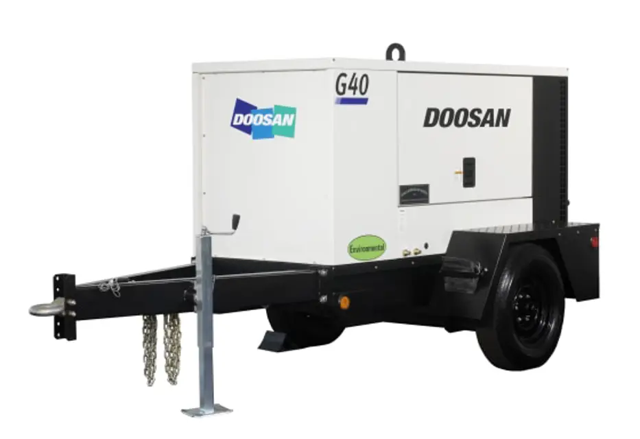
The Doosan Generator G40WMI-2A-T2 (B50) is a robust industrial generator designed for reliable power generation in various applications. Known for its efficiency and durability, this generator model ensures optimal performance and minimal downtime, making it an ideal choice for demanding environments.
Turn manuals into instant answers
with your AI-powered assistantTurn manuals into instant answers
with your AI-powered assistant
Manual for Doosan Doosan Generator G40WMI-2A-T2 (B50) G40WMI-2A-T2 (B50)
Complete asset maintenance, one click away
Get instant access to all the maintenance information you need. Empower technicians to perform preventive maintenance with asset packages, ready to use right out of the box.

Documents & Manuals
Find all the essential guides in one place.
 Tensioning Guide
- Belt-diagram
- C-120 pulleys
+ 13 more

Work Order Templates
Pre-built workflows to keep your asset running smoothly.
- Daily Electrical System Inspection
- Replace Roller and Pulley
- Install Engine B-120
+ 29 more

Procedures
Integrate maintenance plans directly into your work orders.
- Motion Industries
- Applied Industrial Technologies
- Electrical Brothers
+ 5 more

Parts
Access the parts list for your equipment in MaintainX.
- Drive Motor
- B2 Rollers
- Tensioning System
+ 40 more
Doosan Doosan Generator G40WMI-2A-T2 (B50) G40WMI-2A-T2 (B50)
Create an account to install this asset package.
Maintenance Plans for Doosan Doosan Generator G40WMI-2A-T2 (B50) Model G40WMI-2A-T2 (B50)
Integrate maintenance plans directly into your work orders in MaintainX.
1 Daily Engine Check
Check for loose wire routing clamps. Clamps must be secure and properly mounted. Also check wiring for wear, deterioration and vibration abrasion.
Check for evidence of arcing around electrical terminals.
Check that the grounding circuit is in accordance with the National Electrical Code Article 250-122 and the local code requirements. As a minimum, the copper wire size should be American Wire Gauge 8 (AWG#8) from the grounding terminal, frame, generator and engine block.
Check for loose, or frayed wiring insulation or sleeving.
Check for water in the fuel filter/water separator unit. Some engines have a translucent bowl for visual indication, and others have a drain valve below the primary element.
Clean the air vents of any obstruction or debris.
Check Evidence of Arcing around electrical terminals.
Check Loose Wire Routing Clamps.
Check Engine Oil and Coolant Level.

Voltage Regulator Adjustment
With all electric loads disconnected, engine stopped and main breaker turned on, turn VOLTAGE SELECTOR Switch to 277/480V position, and close and latch the VSS door.
Voltage POT(P2) on regulator adjusted to full counterclockwise position
Voltage POT on control panel adjusted to full clockwise position
Start unit.
Verify generator frequency
Set the VOLTAGE OUTPUT MONITOR switch on the control panel to L1-L2 position.
Voltage POT(P2) on the regulator adjusted to read 500V on AC voltmeter
Stability POT(P3) adjusted counter clockwise until the AC volts within ± 1 volt
Then turn the adjusting Stability POT (P3) some 5-10 degrees clockwise.
Alternator Maintenance
Safety Measures
• Servicing or troubleshooting must be carried out strictly in accordance with instructions so as to avoid the risk of accidents and to maintain the machine in its original state.
• All such operations performed on the alternator should be undertaken by personnel with training of electrical and mechanical components.
• Before any intervention on the machine, ensure that it cannot be started by a manual or automatic system and that you have understood the operating principles of the system.
1. Cooling circuit
• It is advisable to check that circulation of air is not reduced by partial blocking of the suction and discharge louvres: mud, fibre, grease, etc.
2. Electrical servicing
• Cleaning product for the windings
WARNING! Do not use: Trichlorethylene, perchlorethylene, trichloroethane and any alkaline products.
250 Hourly / 3 Monthly Engine Maintenance
1. Voltage Selector Door Interlock Switch
• Every three months or 250 operating hours, the interlock switch should be checked. Running with no electric load, open the VOLTAGE SELECTOR door. This will shutdown the engine and trip the main breaker. To reset, close the door.
2. High Containment Fluid Alarm System
• The operation of the high containment fluid alarm system should be checked every 3 months or whenever it appears not to be operating properly.
• The level switch is located at the lower end of a pipe at the bottom of the containment tank.
• Test the switch by unfastening the u-bolts holding the pipe, and then inverting the pipe to allow the switch float to fall.
• The “High Containment Level” LED should illuminate. Replace any defective switch.
• Drain the containment area using the drain plug at either end of the containment basin.;
1 Monthly Engine Maintenance
1. Hoses
• Each month it is recommended that the intake hoses from the air cleaner and all flexible hoses used for water and fuel be inspected for the following:
1) All rubber hose joints and the screw type hose clamps must be tight and the hoses showing no signs of wear, abrasion or deterioration.
2) All flexible hoses must be free of wear, deterioration and vibration abrasion. Routing clamps must be secure and properly mounted.
2. Each month, inspect the radiator exterior for obstructions, dirt and debris. If present, blow water or compressed air containing a non-flammable solvent between the fins in a direction opposite the normal air flow. Should the radiator be clogged internally, reverse flushing, using a commercial product and the supplier’s recommended procedure, may correct the problem.
3. Diagnostic Lamps
• On Keystart models, each month the diagnostic lamps should be tested. With unit shutdown and emergency stop pushed, turn the Engine Start Switch to “START”, or pull the ESTOP to apply power to the controller. All diagnostic lamps should glow; If not, refer to troubleshooting.
4. Diagnostic Trouble Code (DTC) Display
• On models with Electronic (ECU) engines, each month, the DTC display should be tested. When unit is started, the DTC Display should show dashes (---) or a trouble code if there is a fault condition.
Parts for Doosan Doosan Generator G40WMI-2A-T2 (B50) G40WMI-2A-T2 (B50)
Access the parts list for your equipment in MaintainX.
500 Hour Maintenance Kit (& Engine fluids fluids)
44000396
Engine Oil Filter Element
22712467
500 Hour Maintenance Kit (without fluids)
44000412
Engine Fuel Element
22712475
Protec Eng Fluid - 5 gal
54480918
500 Hour Maintenance Kit (& Engine fluids fluids)
44000396
Engine Oil Filter Element
22712467
500 Hour Maintenance Kit (without fluids)
44000412
Engine Fuel Element
22712475
Protec Eng Fluid - 5 gal
54480918
500 Hour Maintenance Kit (& Engine fluids fluids)
44000396
Engine Oil Filter Element
22712467
500 Hour Maintenance Kit (without fluids)
44000412
Engine Fuel Element
22712475
Protec Eng Fluid - 5 gal
54480918
Unlock efficiency
with MaintainX CoPilot
MaintainX CoPilot is your expert colleague, on call 24/7, helping your team find the answers they need to keep equipment running.
Reduce Unplanned Downtime
Ensure your team follows consistent procedures to minimize equipment failures and costly delays.
Maximize Asset Availability
Keep your assets running longer and more reliably, with standardized maintenance workflows from OEM manuals.
Lower Maintenance Costs
Turn any technician into an expert to streamline operations, maintain more assets, and reduce overall costs.
Thousands of companies manage their assets with MaintainX

'%3e%3cpath%20fill='url(%23b)'%20d='M66.008%2080.068c-5.084-.786-9.763-3.834-12.442-8.68a16.942%2016.942%200%200%201-1.87-5.18c1.096.19%202.203.476%203.298.87%206.525%202.333%2010.836%207.68%2011.014%2012.99ZM51.47%2061.576c.488-5.524%203.62-10.716%208.847-13.597a17.132%2017.132%200%200%201%2011.335-1.882c-.798%208.145-7.43%2014.848-16.038%2015.599-1.417.119-2.799.07-4.144-.12Zm28.564-11.478a17.513%2017.513%200%200%201%203.727%204.62c4.608%208.335%201.584%2018.813-6.75%2023.409a16.988%2016.988%200%200%201-4.359%201.679%2019.624%2019.624%200%200%201-3.977-12.776c.346-7.561%204.942-13.931%2011.36-16.932Z'/%3e%3cpath%20fill='%23110F0D'%20fill-rule='evenodd'%20d='M142.831%2048.324h4.977V77.03h-4.977V48.324Zm27.278%2013.002c.322%201.048.453%202.263.453%203.62v12.073h-4.787V66.208c0-.75-.047-1.572-.154-2.143-.453-2.382-1.822-3.572-4.215-3.572-2.31%200-3.882%201.274-4.43%203.476-.143.596-.226%201.405-.226%202.25v10.8h-4.787V56.623h4.477v2.989c1.536-2.5%203.906-3.43%206.371-3.43%203.488%200%206.263%201.68%207.298%205.144Zm24.636%207.323c0%203.882-2.358%206.525-5.763%207.727-1.298.453-2.632.643-4.62.643h-10.169V48.324h9.085c1.691%200%203.156.143%204.049.38%203.465.93%205.727%203.68%205.727%207.335%200%202.441-.81%204.156-2.762%205.644%202.905%201.417%204.453%203.727%204.453%206.966Zm-15.634-8.656h4.584c1.024%200%201.917-.143%202.536-.417%201.215-.548%201.905-1.608%201.905-3.167%200-1.548-.643-2.572-1.845-3.132-.691-.31-1.762-.452-2.763-.452h-4.417v7.168Zm10.716%208.465c0-1.536-.893-3.37-3.227-3.893-.428-.095-1.036-.143-1.571-.143h-5.918v8.085h5.501c.56%200%201.429-.048%201.953-.167%201.94-.453%203.262-1.846%203.262-3.882Zm47.747-11.847-8.097%2020.408h-4.429l-8.109-20.408h5.191l5.192%2014.574%205.108-14.574h5.144Zm-20.218%2010.002c0%20.69-.036%201.262-.155%201.94h-15.943c.631%202.87%202.714%204.728%205.882%204.728%202.131%200%203.607-.882%204.703-2.525h4.87c-1.762%204.144-5.204%206.692-9.657%206.692-6.084%200-10.537-4.858-10.537-10.49%200-6.108%204.524-10.776%2010.335-10.776%206.239%200%2010.442%204.954%2010.502%2010.43Zm-4.763-1.405c-.333-2.846-2.643-4.858-5.691-4.858-2.894%200-5.287%201.929-5.621%204.858h11.312Zm-72.667%203.44c0%204.787-3.287%208.371-9.419%208.371H119.363V64.66c-1.917.274-3.87.69-5.811%201.238l4.537%2011.121h-5.418l-3.596-9.585c-5.144%202.084-10.085%205.216-14.217%209.585h-4.786L101.8%2048.312h4.56l5.68%2013.883a44.112%2044.112%200%200%201%207.323-1.774V48.312h9.084c1.703%200%203.156.143%204.061.393%203.453.929%205.727%203.667%205.727%207.323%200%201.917-.738%204.179-2.81%205.691%203.06%201.56%204.501%204.025%204.501%206.93Zm-15.634-8.667a62.664%2062.664%200%200%201%202.06-.036c1.703.012%203.239.131%204.608.37%201.441-.549%202.357-1.727%202.357-3.537%200-1.941-.881-3.144-2.488-3.667-.548-.18-1.358-.286-2.322-.286h-4.215v7.156Zm-16.55%203.905-3.715-9.894-6.394%2016.502c2.833-2.595%206.263-4.858%2010.109-6.608Zm27.254%204.74c0-2.775-3.131-4.347-8.513-4.418-.715%200-1.441.011-2.191.047v8.252h5.918c2.548%200%204.786-1.37%204.786-3.882Z'%20clip-rule='evenodd'/%3e%3c/g%3e%3cdefs%3e%3clinearGradient%20id='b'%20x1='51.47'%20x2='85.916'%20y1='62.946'%20y2='62.946'%20gradientUnits='userSpaceOnUse'%3e%3cstop%20stop-color='%23CD9F28'/%3e%3cstop%20offset='1'%20stop-color='%23ECD80B'/%3e%3c/linearGradient%3e%3cclipPath%20id='a'%3e%3cpath%20fill='%23fff'%20d='M51.47%2045.728h186.104V80.14H51.47z'/%3e%3c/clipPath%3e%3c/defs%3e%3c/svg%3e)


More from Doosan


Explore Other Assets


© 2025 MaintainX. All rights reserved.