


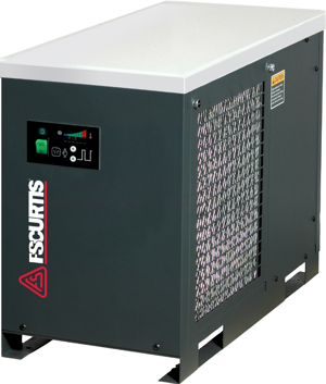
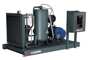
Curtis-Toledo Oil-Injected Rotary Screw Compressor RSB 15
Need answers fast?
Explore the manual using AI.

Turn manuals into instant answers
with your AI-powered assistantTurn manuals into instant answers
with your AI-powered assistant
Manual for Curtis-Toledo Oil-Injected Rotary Screw Compressor RSB 15
Complete asset maintenance, one click away
Get instant access to all the maintenance information you need. Empower technicians to perform preventive maintenance with asset packages, ready to use right out of the box.

Documents & Manuals
Find all the essential guides in one place.
 Tensioning Guide
- Belt-diagram
- C-120 pulleys
+ 13 more

Work Order Templates
Pre-built workflows to keep your asset running smoothly.
- Daily Electrical System Inspection
- Replace Roller and Pulley
- Install Engine B-120
+ 29 more

Procedures
Integrate maintenance plans directly into your work orders.
- Motion Industries
- Applied Industrial Technologies
- Electrical Brothers
+ 5 more

Parts
Access the parts list for your equipment in MaintainX.
- Drive Motor
- B2 Rollers
- Tensioning System
+ 40 more
Curtis-Toledo Oil-Injected Rotary Screw Compressor RSB 15
Create an account to install this asset package.
Maintenance Plans for Curtis-Toledo Oil-Injected Rotary Screw Compressor Model RSB 15
Integrate maintenance plans directly into your work orders in MaintainX.
Standard Air Filter Replacement
Clean the exterior surfaces of the filter canister
Loosen the wing nut and remove the air filter cover
Remove the element and clean the interior surfaces
Inspect and/or replace the element
Replace the cover and retighten the wing nut
Sign off on the air filter replacement

2000 Hourly / 6 Monthly Oil Filter Replacement
WARNING: Before performing any maintenance function, switch main disconnect switch to "off" position to assure no power is entering unit. "Lock Out" or "Tag Out" all sources of power. Be sure all air pressure in unit is relieved. Failure to do this may result in injury or equipment damage.
Shut down the unit, disconnect the power, lockout and tag to prevent accidental restarting.
Wait one (1) minute after the compressor stops to allow for the pressure to be relieved.
Using a strap wrench remove the old filter from the filter head.
Clean the gasket contact surface on the inside of the filter head.
Apply a light film of the compressor oil to the gasket surface on the new element.
Hand tighten the new element until the gasket is seated in the gasket groove.
Continue tightening the element by hand an additional ½ to ¾ turn.
Restart the unit and check for leaks.
Compressor Oil Level Check
DANGER: Hot oil under pressure can cause severe injury, death and/or property damage. Be sure the compressor is shutdown and the pressure is relieved before attempting to change or add lubricant.
Compressor is shut down
Wait one (1) minute after the compressor stops to allow the pressure to be relieved and the lubricant to settle.
Lubricant level is at the center of the sight glass
Power is disconnected, lockout and tag to prevent accidental restarting
Dirt is cleaned from around the fill cap
Cap is loosened and any additional pressure is relieved through the vent holes, then removed
Lubricant is added to the proper level
Cap is replaced and tightened securely
Thermostatic Control Valve Maintenance
In normal operation the thermostatic valve controls the oil temperature and prevents moisture contamination of the oil. Malfunction of this valve may result in moisture in the oil system that can damage the compressor and cause oil carry-over.
A failure of the element in the closed position will divert the lubricant from the oil cooler and result in the unit shutting down due to high temperature.
A repair kit is available for this valve to replace the wearable components. Consult the parts list for your compressor to obtain the part number for this repair kit.
DANGER: Before performing any maintenance be sure the electrical supply has been cut off, locked and tagged and that all pressure has been relieved from the compressor system.
Thermostatic Control Valve Repair (Figure 5-6)
1. Place a spill pan under the valve.
2. Remove the snap ring from the top of the valve body. The valve is spring loaded and the cap may pop up when the ring is removed.
3. Remove the cap and internal parts taking care to note the orientation of the spring, piston and element.
4. Reassemble with the renewal parts. Take care when replacing the cap not to cut the “O” ring or put undue stress on the attached piping.
Initial 100 Hours Drive System Belt Check
Warning: Do not operate the compressor with the fan or belt guard removed. Exposed fan and belts can cause injury to personnel.
DANGER: Before performing any maintenance be sure the electrical supply has been cut off, locked and tagged and that all pressure has been relieved from the compressed air system.
Disconnect the power, lock out and tag out, and allow all pressure to be relieved.
Remove the belt guard.
Inspect for any fraying or cracking. If found replace the belts.
Check the tension. The deflection should be about 1/64” per inch of span between the sheaves with about 4-6 pounds of downward force.
To adjust the tension, loosen the bolts holding the motor to the slide base and using the take-up bolts move the motor until the belts are tight per number 4 above, then retighten the motor bolts.
Replace the belt guard and return the compressor to service.
Sign off on the drive system belt check
Parts for Curtis-Toledo Oil-Injected Rotary Screw Compressor RSB 15
Access the parts list for your equipment in MaintainX.
Oil Analysis Kit
FVO701‐POL
Service Kit
FSK-RS1525
Service Kit
FSK-RS30
Service Kit
FSK-RS4050
Oil Analysis Kit
FVO701‐POL
Service Kit
FSK-RS1525
Service Kit
FSK-RS30
Service Kit
FSK-RS4050
Oil Analysis Kit
FVO701‐POL
Service Kit
FSK-RS1525
Service Kit
FSK-RS30
Service Kit
FSK-RS4050
Unlock efficiency
with MaintainX CoPilot
MaintainX CoPilot is your expert colleague, on call 24/7, helping your team find the answers they need to keep equipment running.
Reduce Unplanned Downtime
Ensure your team follows consistent procedures to minimize equipment failures and costly delays.
Maximize Asset Availability
Keep your assets running longer and more reliably, with standardized maintenance workflows from OEM manuals.
Lower Maintenance Costs
Turn any technician into an expert to streamline operations, maintain more assets, and reduce overall costs.
Thousands of companies manage their assets with MaintainX

'%3e%3cpath%20fill='url(%23b)'%20d='M66.008%2080.068c-5.084-.786-9.763-3.834-12.442-8.68a16.942%2016.942%200%200%201-1.87-5.18c1.096.19%202.203.476%203.298.87%206.525%202.333%2010.836%207.68%2011.014%2012.99ZM51.47%2061.576c.488-5.524%203.62-10.716%208.847-13.597a17.132%2017.132%200%200%201%2011.335-1.882c-.798%208.145-7.43%2014.848-16.038%2015.599-1.417.119-2.799.07-4.144-.12Zm28.564-11.478a17.513%2017.513%200%200%201%203.727%204.62c4.608%208.335%201.584%2018.813-6.75%2023.409a16.988%2016.988%200%200%201-4.359%201.679%2019.624%2019.624%200%200%201-3.977-12.776c.346-7.561%204.942-13.931%2011.36-16.932Z'/%3e%3cpath%20fill='%23110F0D'%20fill-rule='evenodd'%20d='M142.831%2048.324h4.977V77.03h-4.977V48.324Zm27.278%2013.002c.322%201.048.453%202.263.453%203.62v12.073h-4.787V66.208c0-.75-.047-1.572-.154-2.143-.453-2.382-1.822-3.572-4.215-3.572-2.31%200-3.882%201.274-4.43%203.476-.143.596-.226%201.405-.226%202.25v10.8h-4.787V56.623h4.477v2.989c1.536-2.5%203.906-3.43%206.371-3.43%203.488%200%206.263%201.68%207.298%205.144Zm24.636%207.323c0%203.882-2.358%206.525-5.763%207.727-1.298.453-2.632.643-4.62.643h-10.169V48.324h9.085c1.691%200%203.156.143%204.049.38%203.465.93%205.727%203.68%205.727%207.335%200%202.441-.81%204.156-2.762%205.644%202.905%201.417%204.453%203.727%204.453%206.966Zm-15.634-8.656h4.584c1.024%200%201.917-.143%202.536-.417%201.215-.548%201.905-1.608%201.905-3.167%200-1.548-.643-2.572-1.845-3.132-.691-.31-1.762-.452-2.763-.452h-4.417v7.168Zm10.716%208.465c0-1.536-.893-3.37-3.227-3.893-.428-.095-1.036-.143-1.571-.143h-5.918v8.085h5.501c.56%200%201.429-.048%201.953-.167%201.94-.453%203.262-1.846%203.262-3.882Zm47.747-11.847-8.097%2020.408h-4.429l-8.109-20.408h5.191l5.192%2014.574%205.108-14.574h5.144Zm-20.218%2010.002c0%20.69-.036%201.262-.155%201.94h-15.943c.631%202.87%202.714%204.728%205.882%204.728%202.131%200%203.607-.882%204.703-2.525h4.87c-1.762%204.144-5.204%206.692-9.657%206.692-6.084%200-10.537-4.858-10.537-10.49%200-6.108%204.524-10.776%2010.335-10.776%206.239%200%2010.442%204.954%2010.502%2010.43Zm-4.763-1.405c-.333-2.846-2.643-4.858-5.691-4.858-2.894%200-5.287%201.929-5.621%204.858h11.312Zm-72.667%203.44c0%204.787-3.287%208.371-9.419%208.371H119.363V64.66c-1.917.274-3.87.69-5.811%201.238l4.537%2011.121h-5.418l-3.596-9.585c-5.144%202.084-10.085%205.216-14.217%209.585h-4.786L101.8%2048.312h4.56l5.68%2013.883a44.112%2044.112%200%200%201%207.323-1.774V48.312h9.084c1.703%200%203.156.143%204.061.393%203.453.929%205.727%203.667%205.727%207.323%200%201.917-.738%204.179-2.81%205.691%203.06%201.56%204.501%204.025%204.501%206.93Zm-15.634-8.667a62.664%2062.664%200%200%201%202.06-.036c1.703.012%203.239.131%204.608.37%201.441-.549%202.357-1.727%202.357-3.537%200-1.941-.881-3.144-2.488-3.667-.548-.18-1.358-.286-2.322-.286h-4.215v7.156Zm-16.55%203.905-3.715-9.894-6.394%2016.502c2.833-2.595%206.263-4.858%2010.109-6.608Zm27.254%204.74c0-2.775-3.131-4.347-8.513-4.418-.715%200-1.441.011-2.191.047v8.252h5.918c2.548%200%204.786-1.37%204.786-3.882Z'%20clip-rule='evenodd'/%3e%3c/g%3e%3cdefs%3e%3clinearGradient%20id='b'%20x1='51.47'%20x2='85.916'%20y1='62.946'%20y2='62.946'%20gradientUnits='userSpaceOnUse'%3e%3cstop%20stop-color='%23CD9F28'/%3e%3cstop%20offset='1'%20stop-color='%23ECD80B'/%3e%3c/linearGradient%3e%3cclipPath%20id='a'%3e%3cpath%20fill='%23fff'%20d='M51.47%2045.728h186.104V80.14H51.47z'/%3e%3c/clipPath%3e%3c/defs%3e%3c/svg%3e)


More from Curtis-Toledo


Explore Other Assets


© 2026 MaintainX. All rights reserved.