


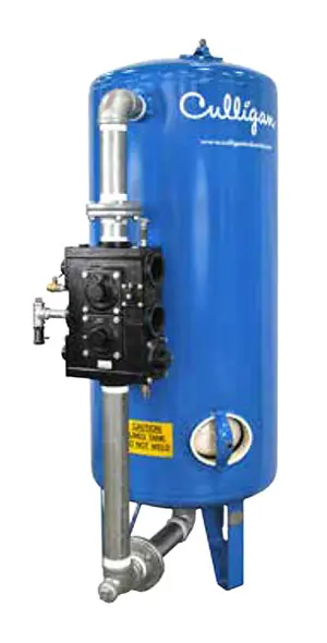
Culligan International Water Softener CSM-750-2
Need answers fast?
Explore the manual using AI.

Turn manuals into instant answers
with your AI-powered assistantTurn manuals into instant answers
with your AI-powered assistant
Manual for Culligan International Water Softener CSM-750-2
Complete asset maintenance, one click away
Get instant access to all the maintenance information you need. Empower technicians to perform preventive maintenance with asset packages, ready to use right out of the box.

Documents & Manuals
Find all the essential guides in one place.
 Tensioning Guide
- Belt-diagram
- C-120 pulleys
+ 13 more

Work Order Templates
Pre-built workflows to keep your asset running smoothly.
- Daily Electrical System Inspection
- Replace Roller and Pulley
- Install Engine B-120
+ 29 more

Procedures
Integrate maintenance plans directly into your work orders.
- Motion Industries
- Applied Industrial Technologies
- Electrical Brothers
+ 5 more

Parts
Access the parts list for your equipment in MaintainX.
- Drive Motor
- B2 Rollers
- Tensioning System
+ 40 more
Culligan International Water Softener CSM-750-2
Create an account to install this asset package.
Maintenance Plans for Culligan International Water Softener Model CSM-750-2
Integrate maintenance plans directly into your work orders in MaintainX.
Pilot Drive Motor Assembly Replacement
Refer to steps 1 thru 5 under 'Pilot Valve Assembly Removal'
The pilot valve drive motor assembly is held in place with 3 panhead screws. Remove the screws and disconnect the motor leads
NOTE At this point it is also advisable to visually inspect the cam gear and microswitches for any wear indicating the need for replacement
Install the replacement pilot valve drive motor assembly making certain that the gears and assembly are properly engaged. Securely tighten the 3 screws and reconnect the motor leads
Reinstall the pilot valve body assembly in the enclosure. Make certain the pilot valve position faces left when viewed from the front of the controller. Reconnect the four quick connect wire leads to the microswitches
Connect the two motor leads to the circuit board. Reconnect all pilot valve tube connections

Brunermatic Valve Depressurization
Warning: Ensure you are working on the correct system
Electrical power to the MVP controller disconnected
By-pass valve opened
Inlet isolation valve closed
Outlet isolation valve closed
Manual brine valve closed
Separate source isolation valve closed
External source of pressure to the pilot valve closed
Position dial on the pilot valve rotated to position #1
Pilot Valve Assembly Removal
Refer to steps 1 thru 3 under 'Pilot Valve Spool Removal & Replacement' on page 71.
Mark and remove all pilot valve tube connections from the pilot valve body.
Disconnect the four quick connect wire leads from the microswitches. Also disconnect the two motor leads from the circuit board. See Figure 115 and Figure 116.
Remove the 2 large panhead screws with nuts located at the bottom of the enclosure that secure the pilot valve body assembly. The pilot body assembly will now separate from the enclosure.
Refer to 'Pilot Valve Assembly Replacement' on page 73 for reinstallation instructions.
Pilot Valve Spool Removal & Replacement
Close the manual inlet isolation valve, the manual outlet isolation valve, the manual brine valve, and any external source of pressure to the pilot valve assembly
Depressurize the system following the instructions on page 65
Disconnect the power to the MVP controller
Manually rotate the position dial on the pilot valve clockwise to position #1 to relieve pressure. Allow the flow of water to drain to stop
Remove the panhead retaining screw located at the bottom front portion of the pilot valve body. Grasp the position dial and pull the pilot valve spool assembly from the pilot valve body
Using a screw driver, gently pry the retaining clip off of the pilot valve spool
LIGHTLY lubricate all seals on the replacement pilot valve spool with Dow Corning #11 silicone grease and assemble the position dial onto the pilot valve spool assembly
Insert the new pilot valve spool assembly into the pilot valve body. Make sure that the #1 on the position dial aligns with the pilot valve body position indicator arrow
Replace the small panhead retaining screw to secure the pilot valve spool assembly into the pilot valve body. Open the manual inlet isolation valve
Backwash Flow Controllers Service
Warning: This service requires trained personnel with PPE!
Is the Backwash Flow Controller plugged with scale, rust, or other foreign material?
If the Backwash Flow Controller is not plugged, report the status to the maintenance team and stop the procedure
Was the cleaning of the Backwash Flow Controller successful?
Enter the backwash flow rate after cleaning
Sign off on the Backwash Flow Controllers Service
Parts for Culligan International Water Softener CSM-750-2
Access the parts list for your equipment in MaintainX.
Tank 100 Psi 36X60-2"
01020126
Tank 125 Psi 36X60-2"
01020132
20"-24" Diameter Non-Code Tanks Handhole Cover Lined W/0.75" Hole 4X6
01019556
20"-24" Diameter Non-Code Tanks Handhole Cover Lined No Hole 4X6
00770902
20"-24" Diameter Non-Code Tanks Gasket 4X6
00770102
Tank 100 Psi 36X60-2"
01020126
Tank 125 Psi 36X60-2"
01020132
20"-24" Diameter Non-Code Tanks Handhole Cover Lined W/0.75" Hole 4X6
01019556
20"-24" Diameter Non-Code Tanks Handhole Cover Lined No Hole 4X6
00770902
20"-24" Diameter Non-Code Tanks Gasket 4X6
00770102
Tank 100 Psi 36X60-2"
01020126
Tank 125 Psi 36X60-2"
01020132
20"-24" Diameter Non-Code Tanks Handhole Cover Lined W/0.75" Hole 4X6
01019556
20"-24" Diameter Non-Code Tanks Handhole Cover Lined No Hole 4X6
00770902
20"-24" Diameter Non-Code Tanks Gasket 4X6
00770102
Unlock efficiency
with MaintainX CoPilot
MaintainX CoPilot is your expert colleague, on call 24/7, helping your team find the answers they need to keep equipment running.
Reduce Unplanned Downtime
Ensure your team follows consistent procedures to minimize equipment failures and costly delays.
Maximize Asset Availability
Keep your assets running longer and more reliably, with standardized maintenance workflows from OEM manuals.
Lower Maintenance Costs
Turn any technician into an expert to streamline operations, maintain more assets, and reduce overall costs.
Thousands of companies manage their assets with MaintainX

'%3e%3cpath%20fill='url(%23b)'%20d='M66.008%2080.068c-5.084-.786-9.763-3.834-12.442-8.68a16.942%2016.942%200%200%201-1.87-5.18c1.096.19%202.203.476%203.298.87%206.525%202.333%2010.836%207.68%2011.014%2012.99ZM51.47%2061.576c.488-5.524%203.62-10.716%208.847-13.597a17.132%2017.132%200%200%201%2011.335-1.882c-.798%208.145-7.43%2014.848-16.038%2015.599-1.417.119-2.799.07-4.144-.12Zm28.564-11.478a17.513%2017.513%200%200%201%203.727%204.62c4.608%208.335%201.584%2018.813-6.75%2023.409a16.988%2016.988%200%200%201-4.359%201.679%2019.624%2019.624%200%200%201-3.977-12.776c.346-7.561%204.942-13.931%2011.36-16.932Z'/%3e%3cpath%20fill='%23110F0D'%20fill-rule='evenodd'%20d='M142.831%2048.324h4.977V77.03h-4.977V48.324Zm27.278%2013.002c.322%201.048.453%202.263.453%203.62v12.073h-4.787V66.208c0-.75-.047-1.572-.154-2.143-.453-2.382-1.822-3.572-4.215-3.572-2.31%200-3.882%201.274-4.43%203.476-.143.596-.226%201.405-.226%202.25v10.8h-4.787V56.623h4.477v2.989c1.536-2.5%203.906-3.43%206.371-3.43%203.488%200%206.263%201.68%207.298%205.144Zm24.636%207.323c0%203.882-2.358%206.525-5.763%207.727-1.298.453-2.632.643-4.62.643h-10.169V48.324h9.085c1.691%200%203.156.143%204.049.38%203.465.93%205.727%203.68%205.727%207.335%200%202.441-.81%204.156-2.762%205.644%202.905%201.417%204.453%203.727%204.453%206.966Zm-15.634-8.656h4.584c1.024%200%201.917-.143%202.536-.417%201.215-.548%201.905-1.608%201.905-3.167%200-1.548-.643-2.572-1.845-3.132-.691-.31-1.762-.452-2.763-.452h-4.417v7.168Zm10.716%208.465c0-1.536-.893-3.37-3.227-3.893-.428-.095-1.036-.143-1.571-.143h-5.918v8.085h5.501c.56%200%201.429-.048%201.953-.167%201.94-.453%203.262-1.846%203.262-3.882Zm47.747-11.847-8.097%2020.408h-4.429l-8.109-20.408h5.191l5.192%2014.574%205.108-14.574h5.144Zm-20.218%2010.002c0%20.69-.036%201.262-.155%201.94h-15.943c.631%202.87%202.714%204.728%205.882%204.728%202.131%200%203.607-.882%204.703-2.525h4.87c-1.762%204.144-5.204%206.692-9.657%206.692-6.084%200-10.537-4.858-10.537-10.49%200-6.108%204.524-10.776%2010.335-10.776%206.239%200%2010.442%204.954%2010.502%2010.43Zm-4.763-1.405c-.333-2.846-2.643-4.858-5.691-4.858-2.894%200-5.287%201.929-5.621%204.858h11.312Zm-72.667%203.44c0%204.787-3.287%208.371-9.419%208.371H119.363V64.66c-1.917.274-3.87.69-5.811%201.238l4.537%2011.121h-5.418l-3.596-9.585c-5.144%202.084-10.085%205.216-14.217%209.585h-4.786L101.8%2048.312h4.56l5.68%2013.883a44.112%2044.112%200%200%201%207.323-1.774V48.312h9.084c1.703%200%203.156.143%204.061.393%203.453.929%205.727%203.667%205.727%207.323%200%201.917-.738%204.179-2.81%205.691%203.06%201.56%204.501%204.025%204.501%206.93Zm-15.634-8.667a62.664%2062.664%200%200%201%202.06-.036c1.703.012%203.239.131%204.608.37%201.441-.549%202.357-1.727%202.357-3.537%200-1.941-.881-3.144-2.488-3.667-.548-.18-1.358-.286-2.322-.286h-4.215v7.156Zm-16.55%203.905-3.715-9.894-6.394%2016.502c2.833-2.595%206.263-4.858%2010.109-6.608Zm27.254%204.74c0-2.775-3.131-4.347-8.513-4.418-.715%200-1.441.011-2.191.047v8.252h5.918c2.548%200%204.786-1.37%204.786-3.882Z'%20clip-rule='evenodd'/%3e%3c/g%3e%3cdefs%3e%3clinearGradient%20id='b'%20x1='51.47'%20x2='85.916'%20y1='62.946'%20y2='62.946'%20gradientUnits='userSpaceOnUse'%3e%3cstop%20stop-color='%23CD9F28'/%3e%3cstop%20offset='1'%20stop-color='%23ECD80B'/%3e%3c/linearGradient%3e%3cclipPath%20id='a'%3e%3cpath%20fill='%23fff'%20d='M51.47%2045.728h186.104V80.14H51.47z'/%3e%3c/clipPath%3e%3c/defs%3e%3c/svg%3e)


More from Culligan International


Explore Other Assets


© 2026 MaintainX. All rights reserved.