


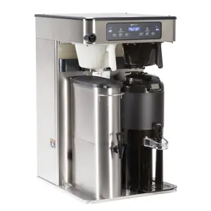
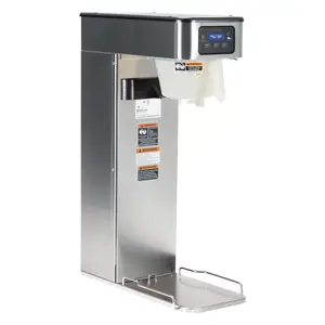
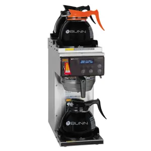
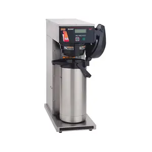
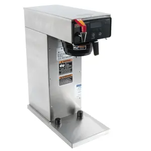
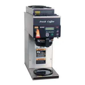
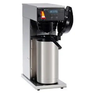
Bunn Brewer CDBCF
Need answers fast?
Explore the manual using AI.
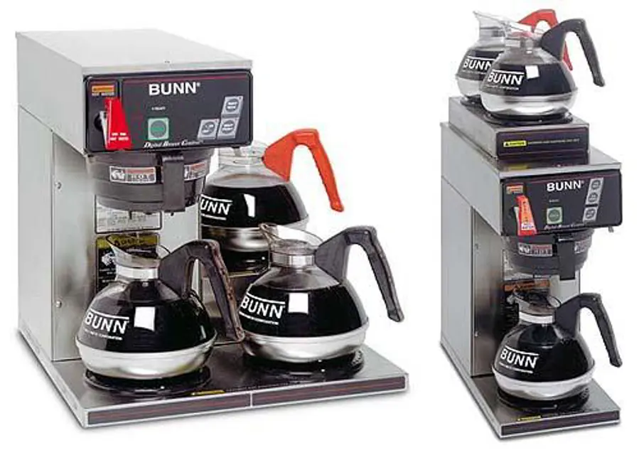
The Bunn Brewer CDBCF is a high-performance commercial coffee brewing system designed for efficiency and reliability. This model features advanced brewing technology, ensuring optimal flavor extraction and consistent results for any coffee establishment. Ideal for cafes and restaurants, the Bunn CDBCF enhances beverage quality while streamlining operations.
Turn manuals into instant answers
with your AI-powered assistantTurn manuals into instant answers
with your AI-powered assistant
Manual for Bunn Brewer CDBCF
Complete asset maintenance, one click away
Get instant access to all the maintenance information you need. Empower technicians to perform preventive maintenance with asset packages, ready to use right out of the box.

Documents & Manuals
Find all the essential guides in one place.
 Tensioning Guide
- Belt-diagram
- C-120 pulleys
+ 13 more

Work Order Templates
Pre-built workflows to keep your asset running smoothly.
- Daily Electrical System Inspection
- Replace Roller and Pulley
- Install Engine B-120
+ 29 more

Procedures
Integrate maintenance plans directly into your work orders.
- Motion Industries
- Applied Industrial Technologies
- Electrical Brothers
+ 5 more

Parts
Access the parts list for your equipment in MaintainX.
- Drive Motor
- B2 Rollers
- Tensioning System
+ 40 more
Bunn Brewer CDBCF
Create an account to install this asset package.
Maintenance Plans for Bunn Brewer Model CDBCF
Integrate maintenance plans directly into your work orders in MaintainX.
Brewer Control Board Maintenance
Warning: This maintenance check requires trained personnel with PPE!
Test the Brewer Control Board
If the control board fails the test, proceed to replace the Brewer Control Board
Disconnect the black wire and blue wire from the relay on the control board
Disconnect the 10-pin connector and the 4-pin connector from the main wiring harness
Disconnect the 11-pin connector from the control panel
Remove the four #6 screws and four nylon washers and the two #4-40 screws securing the control board to the end cap assembly
Install a new control board and secure with the four #6 screws and nylon washers and the two #4- 40 screws to the end cap assembly
NOTE: The four nylon washers must be installed under the heads of the four #6 screws to prevent a possible shorting of the control board circuits

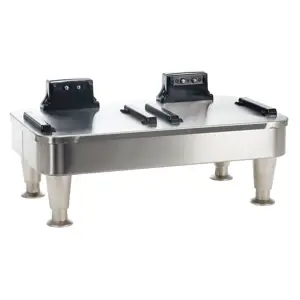
Brewer Warmer Elements Replacement
Remove the three #4-40 screws securing the warmer assembly to the brewer
Lift the warmer assembly from the brewer
Disconnect the two wires from the warmer element terminals
Remove the two #8-32 nuts securing the warmer element to the warmer plate
Securely install new warmer element
Reconnect the two wires to warmer element terminals
Securely install warmer assembly on the brewer
Reconnect the wires
Sign off on the brewer warmer elements replacement
Brewer Tank Heater Test
Warning: Disconnect the brewer from the power source before starting the test
Voltage across the white or red wire from the terminal block and black wire from the control board is 120 volts ac for two wire 120 volt models or 208-240 volts ac for three wire 120/208-240 volt models
Voltage across the red wire from the terminal block and black wire from the control board is 208 or 240 volts ac
Is voltage present as described?
If voltage is not present as described, check wiring harness
Disconnect the black and blue wires or the red and white/violet wires from the tank heater terminals
Continuity is present across tank heater terminals
If continuity is not present as described, replace the tank heater
Is the tank heater able to heat?
Brewer Cleaning
Warning: Always unplug the equipment before cleaning
Cleaned all surfaces with a damp cloth rinsed in mild, nonabrasive, liquid detergent
Checked and cleaned the sprayhead
Ensured the sprayhead holes are open
Sign off on the brewer cleaning
Brewer Tank Heater Replacement
Remove the top cover or top warmer housing and front access panel
Disconnect the vent hose from the top of the tank
Drain water from the tank
Disconnect the water supply tube to the dispense valve from the side of the tank
Disconnect the water supply tube to the solenoid valve from the bottom of the tank
On brewers with faucet, disconnect the outlet water line to the faucet from the side of the tank
Disconnect the temperature probe from the top of the tank
Disconnect the pink wire from the level probe
Disconnect the green wire from the top of the tank
Parts for Bunn Brewer CDBCF
Access the parts list for your equipment in MaintainX.
Cover
23260.1005
Screw
01303.0002
Decal
29206.0000
Screw
01326.0007
Shield
25151.0001
Cover
23260.1005
Screw
01303.0002
Decal
29206.0000
Screw
01326.0007
Shield
25151.0001
Cover
23260.1005
Screw
01303.0002
Decal
29206.0000
Screw
01326.0007
Shield
25151.0001
Unlock efficiency
with MaintainX CoPilot
MaintainX CoPilot is your expert colleague, on call 24/7, helping your team find the answers they need to keep equipment running.
Reduce Unplanned Downtime
Ensure your team follows consistent procedures to minimize equipment failures and costly delays.
Maximize Asset Availability
Keep your assets running longer and more reliably, with standardized maintenance workflows from OEM manuals.
Lower Maintenance Costs
Turn any technician into an expert to streamline operations, maintain more assets, and reduce overall costs.
Thousands of companies manage their assets with MaintainX

'%3e%3cpath%20fill='url(%23b)'%20d='M66.008%2080.068c-5.084-.786-9.763-3.834-12.442-8.68a16.942%2016.942%200%200%201-1.87-5.18c1.096.19%202.203.476%203.298.87%206.525%202.333%2010.836%207.68%2011.014%2012.99ZM51.47%2061.576c.488-5.524%203.62-10.716%208.847-13.597a17.132%2017.132%200%200%201%2011.335-1.882c-.798%208.145-7.43%2014.848-16.038%2015.599-1.417.119-2.799.07-4.144-.12Zm28.564-11.478a17.513%2017.513%200%200%201%203.727%204.62c4.608%208.335%201.584%2018.813-6.75%2023.409a16.988%2016.988%200%200%201-4.359%201.679%2019.624%2019.624%200%200%201-3.977-12.776c.346-7.561%204.942-13.931%2011.36-16.932Z'/%3e%3cpath%20fill='%23110F0D'%20fill-rule='evenodd'%20d='M142.831%2048.324h4.977V77.03h-4.977V48.324Zm27.278%2013.002c.322%201.048.453%202.263.453%203.62v12.073h-4.787V66.208c0-.75-.047-1.572-.154-2.143-.453-2.382-1.822-3.572-4.215-3.572-2.31%200-3.882%201.274-4.43%203.476-.143.596-.226%201.405-.226%202.25v10.8h-4.787V56.623h4.477v2.989c1.536-2.5%203.906-3.43%206.371-3.43%203.488%200%206.263%201.68%207.298%205.144Zm24.636%207.323c0%203.882-2.358%206.525-5.763%207.727-1.298.453-2.632.643-4.62.643h-10.169V48.324h9.085c1.691%200%203.156.143%204.049.38%203.465.93%205.727%203.68%205.727%207.335%200%202.441-.81%204.156-2.762%205.644%202.905%201.417%204.453%203.727%204.453%206.966Zm-15.634-8.656h4.584c1.024%200%201.917-.143%202.536-.417%201.215-.548%201.905-1.608%201.905-3.167%200-1.548-.643-2.572-1.845-3.132-.691-.31-1.762-.452-2.763-.452h-4.417v7.168Zm10.716%208.465c0-1.536-.893-3.37-3.227-3.893-.428-.095-1.036-.143-1.571-.143h-5.918v8.085h5.501c.56%200%201.429-.048%201.953-.167%201.94-.453%203.262-1.846%203.262-3.882Zm47.747-11.847-8.097%2020.408h-4.429l-8.109-20.408h5.191l5.192%2014.574%205.108-14.574h5.144Zm-20.218%2010.002c0%20.69-.036%201.262-.155%201.94h-15.943c.631%202.87%202.714%204.728%205.882%204.728%202.131%200%203.607-.882%204.703-2.525h4.87c-1.762%204.144-5.204%206.692-9.657%206.692-6.084%200-10.537-4.858-10.537-10.49%200-6.108%204.524-10.776%2010.335-10.776%206.239%200%2010.442%204.954%2010.502%2010.43Zm-4.763-1.405c-.333-2.846-2.643-4.858-5.691-4.858-2.894%200-5.287%201.929-5.621%204.858h11.312Zm-72.667%203.44c0%204.787-3.287%208.371-9.419%208.371H119.363V64.66c-1.917.274-3.87.69-5.811%201.238l4.537%2011.121h-5.418l-3.596-9.585c-5.144%202.084-10.085%205.216-14.217%209.585h-4.786L101.8%2048.312h4.56l5.68%2013.883a44.112%2044.112%200%200%201%207.323-1.774V48.312h9.084c1.703%200%203.156.143%204.061.393%203.453.929%205.727%203.667%205.727%207.323%200%201.917-.738%204.179-2.81%205.691%203.06%201.56%204.501%204.025%204.501%206.93Zm-15.634-8.667a62.664%2062.664%200%200%201%202.06-.036c1.703.012%203.239.131%204.608.37%201.441-.549%202.357-1.727%202.357-3.537%200-1.941-.881-3.144-2.488-3.667-.548-.18-1.358-.286-2.322-.286h-4.215v7.156Zm-16.55%203.905-3.715-9.894-6.394%2016.502c2.833-2.595%206.263-4.858%2010.109-6.608Zm27.254%204.74c0-2.775-3.131-4.347-8.513-4.418-.715%200-1.441.011-2.191.047v8.252h5.918c2.548%200%204.786-1.37%204.786-3.882Z'%20clip-rule='evenodd'/%3e%3c/g%3e%3cdefs%3e%3clinearGradient%20id='b'%20x1='51.47'%20x2='85.916'%20y1='62.946'%20y2='62.946'%20gradientUnits='userSpaceOnUse'%3e%3cstop%20stop-color='%23CD9F28'/%3e%3cstop%20offset='1'%20stop-color='%23ECD80B'/%3e%3c/linearGradient%3e%3cclipPath%20id='a'%3e%3cpath%20fill='%23fff'%20d='M51.47%2045.728h186.104V80.14H51.47z'/%3e%3c/clipPath%3e%3c/defs%3e%3c/svg%3e)


More from Bunn

Explore Other Assets


© 2026 MaintainX. All rights reserved.