


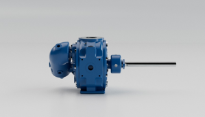
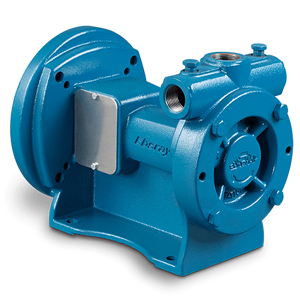
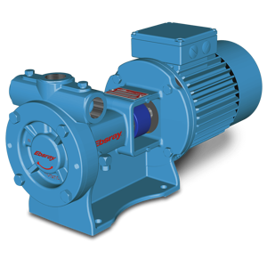
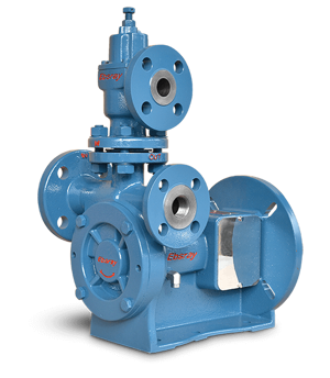
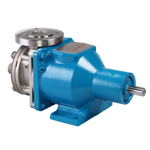
Blackmer Sliding Vane Pump TXD2A
Need answers fast?
Explore the manual using AI.
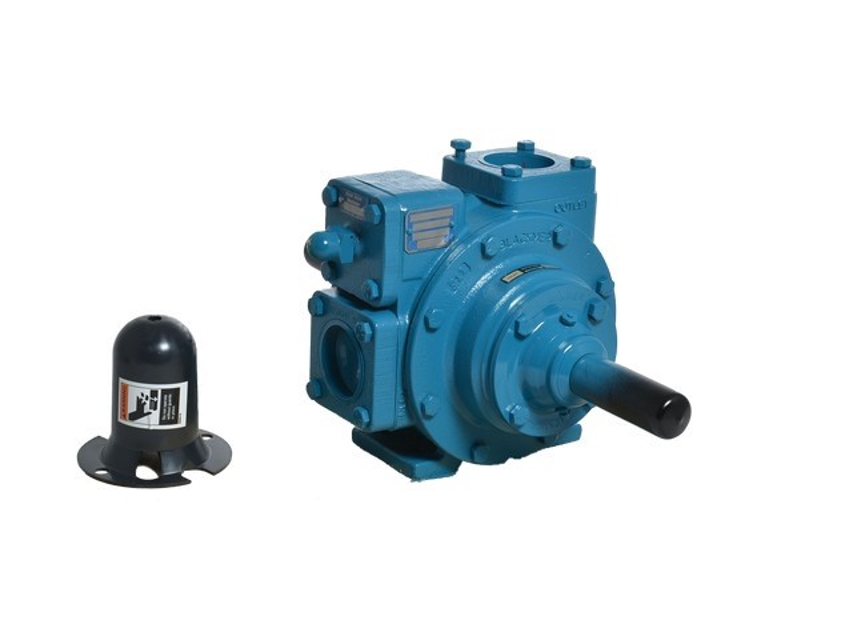
The Blackmer Sliding Vane Pump TXD2A is a reliable and efficient pump designed for various industrial applications. Known for its robust construction and superior performance, this model ensures optimal fluid transfer and handling, making it a preferred choice for professionals in the field.
Turn manuals into instant answers
with your AI-powered assistantTurn manuals into instant answers
with your AI-powered assistant
Manual for Blackmer Sliding Vane Pump TXD2A
Complete asset maintenance, one click away
Get instant access to all the maintenance information you need. Empower technicians to perform preventive maintenance with asset packages, ready to use right out of the box.

Documents & Manuals
Find all the essential guides in one place.
 Tensioning Guide
- Belt-diagram
- C-120 pulleys
+ 13 more

Work Order Templates
Pre-built workflows to keep your asset running smoothly.
- Daily Electrical System Inspection
- Replace Roller and Pulley
- Install Engine B-120
+ 29 more

Procedures
Integrate maintenance plans directly into your work orders.
- Motion Industries
- Applied Industrial Technologies
- Electrical Brothers
+ 5 more

Parts
Access the parts list for your equipment in MaintainX.
- Drive Motor
- B2 Rollers
- Tensioning System
+ 40 more
Blackmer Sliding Vane Pump TXD2A
Create an account to install this asset package.
Maintenance Plans for Blackmer Sliding Vane Pump Model TXD2A
Integrate maintenance plans directly into your work orders in MaintainX.
Vane Replacement
NOTICE: Maintenance shall be performed by qualified technicians only, following the appropriate procedures and warnings as presented in manual
Head assembly removed from the outboard (non-driven) side of the pump
Shaft turned by hand until a vane comes to the top (12 o'clock) position of the rotor
Old vane removed
New vane installed with rounded edge UP, and relief grooves facing towards the direction of rotation
All vanes replaced
Pump reassembled
Technician's signature

3 Monthly Pump Lubrication
NOTICE: To avoid possible entanglement in moving parts do not lubricate pump bearings, hydraulic adapter coupling or any other parts while the pump is running
NOTICE: If pumps are repainted in the field, ensure that the grease relief fittings (76A) are functioning properly after painting. Do NOT paint them closed. Remove any excess paint from the fittings
Lubricate the ball bearings, and hydraulic motor couplings (if equipped), every three months at a minimum
MANUAL Greasing Procedure
Remove the grease relief fittings (76A) from the bearing covers (27A) or hydraulic motor adapter (135)
Apply grease with a hand gun until grease begins to escape from the grease relief fitting port
Replace the grease relief fittings (76A)
DO NOT overgrease pump bearings. While it is normal for some grease to escape from the grease tell-tale hole after lubrication, excessive grease on pumps equipped with mechanical seals can cause seal failure
AUTO Greasing Systems
Strainer Cleaning
NOTICE: Maintenance shall be performed by qualified technicians only, following the appropriate procedures and warnings as presented in this manual
Strainers cleaned regularly to avoid pump starvation
Schedule will depend upon the application and conditions
Technician's signature
Pump Overhaul
NOTICE! Follow all hazard warnings and instructions provided in the 'Maintenance' section of the manual
Clean Pump Shaft. Start on the inboard (driven) end of the pump. Clean the pump shaft thoroughly, ensuring it is free of nicks and burrs. This prevents damage to the mechanical seal when the inboard head assembly is removed
Remove the inboard bearing cover capscrews (28). Slide the inboard bearing cover and gasket off the shaft. Discard the bearing cover gasket
Remove the outboard bearing cover capscrews. Slide the outboard bearing cover and gasket off the shaft. Discard the bearing cover gasket
If equipped with locknuts and lockwashers, bend up the engaged lockwasher tang and rotate the locknut counterclockwise to remove it from the shaft. Slide the lockwasher off the shaft. Inspect the lockwasher for damage and replace as required. Repeat steps on the opposite shaft end
The TX4-inch pump model is equipped with bearing lock collars. To remove, remove the jam nuts and loosen the two set screws. Slide the lock collar off the shaft. Repeat steps on the opposite shaft end
Remove the head capscrews and carefully pry the head away from the cylinder. Slide the head off the shaft. The head O-ring, bearing, and mechanical seal will come off with the head assembly. Remove and discard the head O-ring
Pull the rotor and shaft from the cylinder. While one hand is pulling the shaft, the other hand should be cupped underneath the rotor to prevent the vanes and push rods from falling out. Carefully set the rotor and shaft, vanes, and push rods aside for future vane replacement and reassembly
Remove the remaining components from the outboard side of the pump
Parts for Blackmer Sliding Vane Pump TXD2A
Access the parts list for your equipment in MaintainX.
Cap – Relief Valve (R/V)
411453
Cover – R/V
411401
Adjusting Screw – R/V
431401
Spring – R/V (36-50 psi)
471415
Dirt Shield
701480
Cap – Relief Valve (R/V)
411453
Cover – R/V
411401
Adjusting Screw – R/V
431401
Spring – R/V (36-50 psi)
471415
Dirt Shield
701480
Cap – Relief Valve (R/V)
411453
Cover – R/V
411401
Adjusting Screw – R/V
431401
Spring – R/V (36-50 psi)
471415
Dirt Shield
701480
Unlock efficiency
with MaintainX CoPilot
MaintainX CoPilot is your expert colleague, on call 24/7, helping your team find the answers they need to keep equipment running.
Reduce Unplanned Downtime
Ensure your team follows consistent procedures to minimize equipment failures and costly delays.
Maximize Asset Availability
Keep your assets running longer and more reliably, with standardized maintenance workflows from OEM manuals.
Lower Maintenance Costs
Turn any technician into an expert to streamline operations, maintain more assets, and reduce overall costs.
Thousands of companies manage their assets with MaintainX

'%3e%3cpath%20fill='url(%23b)'%20d='M66.008%2080.068c-5.084-.786-9.763-3.834-12.442-8.68a16.942%2016.942%200%200%201-1.87-5.18c1.096.19%202.203.476%203.298.87%206.525%202.333%2010.836%207.68%2011.014%2012.99ZM51.47%2061.576c.488-5.524%203.62-10.716%208.847-13.597a17.132%2017.132%200%200%201%2011.335-1.882c-.798%208.145-7.43%2014.848-16.038%2015.599-1.417.119-2.799.07-4.144-.12Zm28.564-11.478a17.513%2017.513%200%200%201%203.727%204.62c4.608%208.335%201.584%2018.813-6.75%2023.409a16.988%2016.988%200%200%201-4.359%201.679%2019.624%2019.624%200%200%201-3.977-12.776c.346-7.561%204.942-13.931%2011.36-16.932Z'/%3e%3cpath%20fill='%23110F0D'%20fill-rule='evenodd'%20d='M142.831%2048.324h4.977V77.03h-4.977V48.324Zm27.278%2013.002c.322%201.048.453%202.263.453%203.62v12.073h-4.787V66.208c0-.75-.047-1.572-.154-2.143-.453-2.382-1.822-3.572-4.215-3.572-2.31%200-3.882%201.274-4.43%203.476-.143.596-.226%201.405-.226%202.25v10.8h-4.787V56.623h4.477v2.989c1.536-2.5%203.906-3.43%206.371-3.43%203.488%200%206.263%201.68%207.298%205.144Zm24.636%207.323c0%203.882-2.358%206.525-5.763%207.727-1.298.453-2.632.643-4.62.643h-10.169V48.324h9.085c1.691%200%203.156.143%204.049.38%203.465.93%205.727%203.68%205.727%207.335%200%202.441-.81%204.156-2.762%205.644%202.905%201.417%204.453%203.727%204.453%206.966Zm-15.634-8.656h4.584c1.024%200%201.917-.143%202.536-.417%201.215-.548%201.905-1.608%201.905-3.167%200-1.548-.643-2.572-1.845-3.132-.691-.31-1.762-.452-2.763-.452h-4.417v7.168Zm10.716%208.465c0-1.536-.893-3.37-3.227-3.893-.428-.095-1.036-.143-1.571-.143h-5.918v8.085h5.501c.56%200%201.429-.048%201.953-.167%201.94-.453%203.262-1.846%203.262-3.882Zm47.747-11.847-8.097%2020.408h-4.429l-8.109-20.408h5.191l5.192%2014.574%205.108-14.574h5.144Zm-20.218%2010.002c0%20.69-.036%201.262-.155%201.94h-15.943c.631%202.87%202.714%204.728%205.882%204.728%202.131%200%203.607-.882%204.703-2.525h4.87c-1.762%204.144-5.204%206.692-9.657%206.692-6.084%200-10.537-4.858-10.537-10.49%200-6.108%204.524-10.776%2010.335-10.776%206.239%200%2010.442%204.954%2010.502%2010.43Zm-4.763-1.405c-.333-2.846-2.643-4.858-5.691-4.858-2.894%200-5.287%201.929-5.621%204.858h11.312Zm-72.667%203.44c0%204.787-3.287%208.371-9.419%208.371H119.363V64.66c-1.917.274-3.87.69-5.811%201.238l4.537%2011.121h-5.418l-3.596-9.585c-5.144%202.084-10.085%205.216-14.217%209.585h-4.786L101.8%2048.312h4.56l5.68%2013.883a44.112%2044.112%200%200%201%207.323-1.774V48.312h9.084c1.703%200%203.156.143%204.061.393%203.453.929%205.727%203.667%205.727%207.323%200%201.917-.738%204.179-2.81%205.691%203.06%201.56%204.501%204.025%204.501%206.93Zm-15.634-8.667a62.664%2062.664%200%200%201%202.06-.036c1.703.012%203.239.131%204.608.37%201.441-.549%202.357-1.727%202.357-3.537%200-1.941-.881-3.144-2.488-3.667-.548-.18-1.358-.286-2.322-.286h-4.215v7.156Zm-16.55%203.905-3.715-9.894-6.394%2016.502c2.833-2.595%206.263-4.858%2010.109-6.608Zm27.254%204.74c0-2.775-3.131-4.347-8.513-4.418-.715%200-1.441.011-2.191.047v8.252h5.918c2.548%200%204.786-1.37%204.786-3.882Z'%20clip-rule='evenodd'/%3e%3c/g%3e%3cdefs%3e%3clinearGradient%20id='b'%20x1='51.47'%20x2='85.916'%20y1='62.946'%20y2='62.946'%20gradientUnits='userSpaceOnUse'%3e%3cstop%20stop-color='%23CD9F28'/%3e%3cstop%20offset='1'%20stop-color='%23ECD80B'/%3e%3c/linearGradient%3e%3cclipPath%20id='a'%3e%3cpath%20fill='%23fff'%20d='M51.47%2045.728h186.104V80.14H51.47z'/%3e%3c/clipPath%3e%3c/defs%3e%3c/svg%3e)


More from Blackmer


Explore Other Assets


© 2026 MaintainX. All rights reserved.