


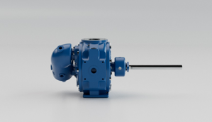
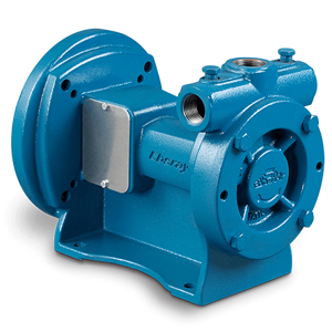
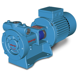
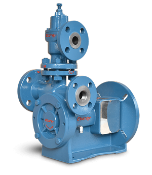
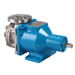
Blackmer Sliding Vane Pump HXL6G
Need answers fast?
Explore the manual using AI.
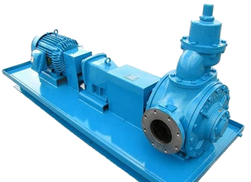
The Blackmer Sliding Vane Pump HXL6G is a robust and efficient pump designed for handling a variety of fluids. Known for its reliability and performance, this OEM model is ideal for industrial applications requiring precise fluid transfer and management. Enhance your operations with the HXL6G's advanced engineering and durable construction.
Turn manuals into instant answers
with your AI-powered assistantTurn manuals into instant answers
with your AI-powered assistant
Manual for Blackmer Sliding Vane Pump HXL6G
Complete asset maintenance, one click away
Get instant access to all the maintenance information you need. Empower technicians to perform preventive maintenance with asset packages, ready to use right out of the box.

Documents & Manuals
Find all the essential guides in one place.
 Tensioning Guide
- Belt-diagram
- C-120 pulleys
+ 13 more

Work Order Templates
Pre-built workflows to keep your asset running smoothly.
- Daily Electrical System Inspection
- Replace Roller and Pulley
- Install Engine B-120
+ 29 more

Procedures
Integrate maintenance plans directly into your work orders.
- Motion Industries
- Applied Industrial Technologies
- Electrical Brothers
+ 5 more

Parts
Access the parts list for your equipment in MaintainX.
- Drive Motor
- B2 Rollers
- Tensioning System
+ 40 more
Blackmer Sliding Vane Pump HXL6G
Create an account to install this asset package.
Maintenance Plans for Blackmer Sliding Vane Pump Model HXL6G
Integrate maintenance plans directly into your work orders in MaintainX.
3 Monthly Pump Lubrication
NOTICE: To avoid possible entanglement in moving parts do not lubricate pump bearings, hydraulic adapter coupling or any other parts while the pump is running
NOTICE: If pumps are repainted in the field, ensure that the grease relief fittings (76A) are functioning properly after painting. Do NOT paint them closed. Remove any excess paint from the fittings
Ball bearings must be lubricated every three months at minimum. More frequent lubrication may be required depending on the application and operating conditions
Greasing Procedure
Remove the grease relief fittings (76A) from the bearing covers (27 and 27A)
SLOWLY apply grease with a hand gun until grease begins to escape from the grease relief fitting port. Discard excess grease in accordance with proper codes and regulations
Replace the grease relief fittings (76A). DO NOT overgrease pump bearings. While it is normal for some grease to escape from the grease tell-tale hole after lubrication, excessive grease can cause mechanical seal failure. The tell-tale hole is located in the head or hub between the bearing and the seal. Lubricate the ball bearings, and hydraulic motor couplings (if equipped), every three months at a minimum
Sign off on the pump lubrication

Vane Replacement
NOTICE: Maintenance shall be performed by qualified technicians only, following the appropriate procedures and warnings as presented in manual
Pump in upright position?
Pump flushed per instructions in manual?
Pressure from the pump and system relieved?
Head assembly removed from the outboard (nondriven) side of the pump?
Vane at the top (12 o'clock) position of the rotor?
Old vane removed?
New vane installed with rounded edge UP and relief grooves facing towards the direction of rotation?
All vanes replaced?
Pump Overhaul
NOTICE: Follow all hazard warnings and instructions provided in the “Maintenance” section of this manual
NOTICE: Use a hoist and appropriate sling or lifting lugs attached to the baseplate to lift the entire pump assembly. Eyebolts attached to the pump, gearbox, or motor must be used to lift that particular component only
NOTICE: Use a hoist and eyebolts installed in the threaded holes located in the heads, discs, rotor and casing to lift the heavy pump parts
Flush the pump per instructions in this manual. Relieve pressure from the pump and system and drain as required
Set the pump upright. Clean the pump shaft thoroughly, making sure the shaft is free of nicks and burrs. This will prevent damage to the mechanical seal when the inboard head assembly is removed
Remove the inboard bearing cover capscrews and slide the inboard bearing cover and gasket off the shaft. Discard the bearing cover gasket
Remove the head capscrews. If necessary, place head capcrews in the two tapped holes near the outer rim of the head and tighten until the head separates from the casing. Use a hoist to remove the head from the casing, being careful not to damage the shaft. The bearing, stationary seat and stationary O-ring will come off with the head assembly
Remove the head O-ring and disc. If needed, threaded holes are provided in the disc to break it free
Remove the top vane then rotate the shaft by hand to bring the next vane to the top until all the vanes have been removed. If the vanes are swollen or jammed in their slots , the rotor-shaft must be removed as described below
Strainer Cleaning
NOTICE: Maintenance shall be performed by qualified technicians only, following the appropriate procedures and warnings as presented in this manual
Strainers must be cleaned regularly to avoid pump starvation
Schedule will depend upon the application and conditions
Strainer cleaned properly
Technician's signature
Parts for Blackmer Sliding Vane Pump HXL6G
Access the parts list for your equipment in MaintainX.
Gasket - Blanking Plate
537252
FS Rotor & Shaft
287239
Kit - Rebuild
899012
Capscrews - Head
920680
Cap – Relief Valve (R/V)
417710
Gasket - Blanking Plate
537252
FS Rotor & Shaft
287239
Kit - Rebuild
899012
Capscrews - Head
920680
Cap – Relief Valve (R/V)
417710
Gasket - Blanking Plate
537252
FS Rotor & Shaft
287239
Kit - Rebuild
899012
Capscrews - Head
920680
Cap – Relief Valve (R/V)
417710
Unlock efficiency
with MaintainX CoPilot
MaintainX CoPilot is your expert colleague, on call 24/7, helping your team find the answers they need to keep equipment running.
Reduce Unplanned Downtime
Ensure your team follows consistent procedures to minimize equipment failures and costly delays.
Maximize Asset Availability
Keep your assets running longer and more reliably, with standardized maintenance workflows from OEM manuals.
Lower Maintenance Costs
Turn any technician into an expert to streamline operations, maintain more assets, and reduce overall costs.
Thousands of companies manage their assets with MaintainX

'%3e%3cpath%20fill='url(%23b)'%20d='M66.008%2080.068c-5.084-.786-9.763-3.834-12.442-8.68a16.942%2016.942%200%200%201-1.87-5.18c1.096.19%202.203.476%203.298.87%206.525%202.333%2010.836%207.68%2011.014%2012.99ZM51.47%2061.576c.488-5.524%203.62-10.716%208.847-13.597a17.132%2017.132%200%200%201%2011.335-1.882c-.798%208.145-7.43%2014.848-16.038%2015.599-1.417.119-2.799.07-4.144-.12Zm28.564-11.478a17.513%2017.513%200%200%201%203.727%204.62c4.608%208.335%201.584%2018.813-6.75%2023.409a16.988%2016.988%200%200%201-4.359%201.679%2019.624%2019.624%200%200%201-3.977-12.776c.346-7.561%204.942-13.931%2011.36-16.932Z'/%3e%3cpath%20fill='%23110F0D'%20fill-rule='evenodd'%20d='M142.831%2048.324h4.977V77.03h-4.977V48.324Zm27.278%2013.002c.322%201.048.453%202.263.453%203.62v12.073h-4.787V66.208c0-.75-.047-1.572-.154-2.143-.453-2.382-1.822-3.572-4.215-3.572-2.31%200-3.882%201.274-4.43%203.476-.143.596-.226%201.405-.226%202.25v10.8h-4.787V56.623h4.477v2.989c1.536-2.5%203.906-3.43%206.371-3.43%203.488%200%206.263%201.68%207.298%205.144Zm24.636%207.323c0%203.882-2.358%206.525-5.763%207.727-1.298.453-2.632.643-4.62.643h-10.169V48.324h9.085c1.691%200%203.156.143%204.049.38%203.465.93%205.727%203.68%205.727%207.335%200%202.441-.81%204.156-2.762%205.644%202.905%201.417%204.453%203.727%204.453%206.966Zm-15.634-8.656h4.584c1.024%200%201.917-.143%202.536-.417%201.215-.548%201.905-1.608%201.905-3.167%200-1.548-.643-2.572-1.845-3.132-.691-.31-1.762-.452-2.763-.452h-4.417v7.168Zm10.716%208.465c0-1.536-.893-3.37-3.227-3.893-.428-.095-1.036-.143-1.571-.143h-5.918v8.085h5.501c.56%200%201.429-.048%201.953-.167%201.94-.453%203.262-1.846%203.262-3.882Zm47.747-11.847-8.097%2020.408h-4.429l-8.109-20.408h5.191l5.192%2014.574%205.108-14.574h5.144Zm-20.218%2010.002c0%20.69-.036%201.262-.155%201.94h-15.943c.631%202.87%202.714%204.728%205.882%204.728%202.131%200%203.607-.882%204.703-2.525h4.87c-1.762%204.144-5.204%206.692-9.657%206.692-6.084%200-10.537-4.858-10.537-10.49%200-6.108%204.524-10.776%2010.335-10.776%206.239%200%2010.442%204.954%2010.502%2010.43Zm-4.763-1.405c-.333-2.846-2.643-4.858-5.691-4.858-2.894%200-5.287%201.929-5.621%204.858h11.312Zm-72.667%203.44c0%204.787-3.287%208.371-9.419%208.371H119.363V64.66c-1.917.274-3.87.69-5.811%201.238l4.537%2011.121h-5.418l-3.596-9.585c-5.144%202.084-10.085%205.216-14.217%209.585h-4.786L101.8%2048.312h4.56l5.68%2013.883a44.112%2044.112%200%200%201%207.323-1.774V48.312h9.084c1.703%200%203.156.143%204.061.393%203.453.929%205.727%203.667%205.727%207.323%200%201.917-.738%204.179-2.81%205.691%203.06%201.56%204.501%204.025%204.501%206.93Zm-15.634-8.667a62.664%2062.664%200%200%201%202.06-.036c1.703.012%203.239.131%204.608.37%201.441-.549%202.357-1.727%202.357-3.537%200-1.941-.881-3.144-2.488-3.667-.548-.18-1.358-.286-2.322-.286h-4.215v7.156Zm-16.55%203.905-3.715-9.894-6.394%2016.502c2.833-2.595%206.263-4.858%2010.109-6.608Zm27.254%204.74c0-2.775-3.131-4.347-8.513-4.418-.715%200-1.441.011-2.191.047v8.252h5.918c2.548%200%204.786-1.37%204.786-3.882Z'%20clip-rule='evenodd'/%3e%3c/g%3e%3cdefs%3e%3clinearGradient%20id='b'%20x1='51.47'%20x2='85.916'%20y1='62.946'%20y2='62.946'%20gradientUnits='userSpaceOnUse'%3e%3cstop%20stop-color='%23CD9F28'/%3e%3cstop%20offset='1'%20stop-color='%23ECD80B'/%3e%3c/linearGradient%3e%3cclipPath%20id='a'%3e%3cpath%20fill='%23fff'%20d='M51.47%2045.728h186.104V80.14H51.47z'/%3e%3c/clipPath%3e%3c/defs%3e%3c/svg%3e)


More from Blackmer


Explore Other Assets


© 2026 MaintainX. All rights reserved.