


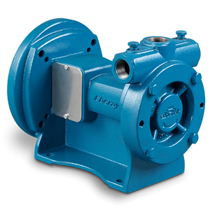
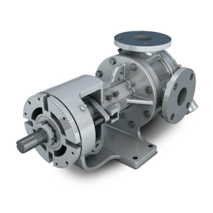
Blackmer Internal Gear Pump V2-133
Need answers fast?
Explore the manual using AI.

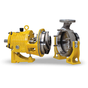
The Blackmer Internal Gear Pump V2-133 is a robust and efficient pump designed for various industrial applications. Known for its reliability and performance, this model excels in transferring viscous fluids while minimizing shear and pulsation. Ideal for demanding environments, the V2-133 ensures optimal operation and longevity.
Turn manuals into instant answers
with your AI-powered assistantTurn manuals into instant answers
with your AI-powered assistant
Manual for Blackmer Internal Gear Pump V2-133
Complete asset maintenance, one click away
Get instant access to all the maintenance information you need. Empower technicians to perform preventive maintenance with asset packages, ready to use right out of the box.

Documents & Manuals
Find all the essential guides in one place.
 Tensioning Guide
- Belt-diagram
- C-120 pulleys
+ 13 more

Work Order Templates
Pre-built workflows to keep your asset running smoothly.
- Daily Electrical System Inspection
- Replace Roller and Pulley
- Install Engine B-120
+ 29 more

Procedures
Integrate maintenance plans directly into your work orders.
- Motion Industries
- Applied Industrial Technologies
- Electrical Brothers
+ 5 more

Parts
Access the parts list for your equipment in MaintainX.
- Drive Motor
- B2 Rollers
- Tensioning System
+ 40 more
Blackmer Internal Gear Pump V2-133
Create an account to install this asset package.
Maintenance Plans for Blackmer Internal Gear Pump Model V2-133
Integrate maintenance plans directly into your work orders in MaintainX.
Internal Gear Pump Overhaul
Remove the screws that hold the head to the casing
Remove the head from the pump using either jacking screws or prying bar
WARNING: Protect the idler gear from falling as it may become loose during removal of the head
Remove the idler gear and bushing assembly
Remove the seal or packing set
Loosen the six (6) mounting fasteners that hold the RBS to the casing or adapter plate. Use provided jacking screws if needed
Carefully remove the rotor/shaft assembly. Threaded screw holes are provided on the end of the rotor for lifting purposes to ease removal
For 55, 133 and 254 size pumps, remove the screws that hold the adapter plate to the casing and remove the adapter plate
For 133, 254 and 423 size pumps, remove the thrust washers from the rotor/shaft assembly and rotor bearing sleeve assembly

Internal Gear Pump Maintenance
V Series pumps must be maintained and kept as clean as possible. This will allow for quick inspection, adjustment and repair work
Frictional wear on internal components of the pump may result in loss of pressure/flow in service due to slip. Pump performance can be improved by adjusting the end play
If a pump is to be stored for more than six (6) months, the pump must be drained prior to storing. A light coat of light oil should be applied to all internal pump parts in order to prevent corrosion.
Operators should also lubricate the fittings and apply grease to the pump shaft, while periodically rotating the pump shaft by hand one (1) complete revolution every 30 days to circulate the oil
Be sure to inspect the fastener torque before putting the pump in service after being stored
Sign off on the pump maintenance
Cartridge Triple -Lip Seal Maintenance
Warning: This maintenance check requires trained personnel with PPE!
Disconnect all flush lines or barrier fluid tubes
Loosen the set screws on the seal collar to free the cartridge seal from the shaft
Remove the two (2) fasteners from the seal gland
Slide the cartridge seal out of the stuffing box
Clean the rotor shaft and the seal housing bore (stuffing box)
Lubricate the rotor shaft and inside diameter of the seal generously with light oil
Slide the cartridge seal over the shaft until it contacts the seal chamber face
Install the gland and nuts
Internal Gear Pump Standard Packing Maintenance
PACKING ADJUSTMENT
Newly packed pumps require initial packing adjustments to control leakage
Small initial adjustments are needed to prevent over-tightening of the packing gland
After initial startup, additional adjustments may be required
The packing should also be checked periodically and adjusted as needed
REMOVAL
Remove packing gland fasteners
Slide the packing gland along the shaft out of the stuffing box
Remove the packing
500 Hourly Internal Gear Pump Lubrication
Warning: This procedure requires trained personnel with PPE!
Multi-purpose NLGI #2 grease used on all lubrication fittings?
Over-greasing avoided?
Was the operation under extreme temperatures?
If operation was under extreme temperatures, consult factory for specific lubrication recommendations
Sign off on the lubrication procedure
Parts for Blackmer Internal Gear Pump V2-133
Access the parts list for your equipment in MaintainX.
Stud, Double End, 5/8"-11 X 3", Carbon Steel/Zinc Plated
T09C625C00WA2A2
Bushing, RBS, V-133/254, Bronze
1330-2840-320
Valve, ASM, G1-133/222, V-133, 50 PSI, Cast Iron
1330-7001-110
Valve, ASM, G1-133/222, V-133, 75 PSI, Cast Iron
1330-7002-110
Plug, Pipe, 3/4" NPT, Carbon Steel/Zinc Plated
PLUG-075NSH-230
Unlock efficiency
with MaintainX CoPilot
MaintainX CoPilot is your expert colleague, on call 24/7, helping your team find the answers they need to keep equipment running.
Reduce Unplanned Downtime
Ensure your team follows consistent procedures to minimize equipment failures and costly delays.
Maximize Asset Availability
Keep your assets running longer and more reliably, with standardized maintenance workflows from OEM manuals.
Lower Maintenance Costs
Turn any technician into an expert to streamline operations, maintain more assets, and reduce overall costs.
Thousands of companies manage their assets with MaintainX

'%3e%3cpath%20fill='url(%23b)'%20d='M66.008%2080.068c-5.084-.786-9.763-3.834-12.442-8.68a16.942%2016.942%200%200%201-1.87-5.18c1.096.19%202.203.476%203.298.87%206.525%202.333%2010.836%207.68%2011.014%2012.99ZM51.47%2061.576c.488-5.524%203.62-10.716%208.847-13.597a17.132%2017.132%200%200%201%2011.335-1.882c-.798%208.145-7.43%2014.848-16.038%2015.599-1.417.119-2.799.07-4.144-.12Zm28.564-11.478a17.513%2017.513%200%200%201%203.727%204.62c4.608%208.335%201.584%2018.813-6.75%2023.409a16.988%2016.988%200%200%201-4.359%201.679%2019.624%2019.624%200%200%201-3.977-12.776c.346-7.561%204.942-13.931%2011.36-16.932Z'/%3e%3cpath%20fill='%23110F0D'%20fill-rule='evenodd'%20d='M142.831%2048.324h4.977V77.03h-4.977V48.324Zm27.278%2013.002c.322%201.048.453%202.263.453%203.62v12.073h-4.787V66.208c0-.75-.047-1.572-.154-2.143-.453-2.382-1.822-3.572-4.215-3.572-2.31%200-3.882%201.274-4.43%203.476-.143.596-.226%201.405-.226%202.25v10.8h-4.787V56.623h4.477v2.989c1.536-2.5%203.906-3.43%206.371-3.43%203.488%200%206.263%201.68%207.298%205.144Zm24.636%207.323c0%203.882-2.358%206.525-5.763%207.727-1.298.453-2.632.643-4.62.643h-10.169V48.324h9.085c1.691%200%203.156.143%204.049.38%203.465.93%205.727%203.68%205.727%207.335%200%202.441-.81%204.156-2.762%205.644%202.905%201.417%204.453%203.727%204.453%206.966Zm-15.634-8.656h4.584c1.024%200%201.917-.143%202.536-.417%201.215-.548%201.905-1.608%201.905-3.167%200-1.548-.643-2.572-1.845-3.132-.691-.31-1.762-.452-2.763-.452h-4.417v7.168Zm10.716%208.465c0-1.536-.893-3.37-3.227-3.893-.428-.095-1.036-.143-1.571-.143h-5.918v8.085h5.501c.56%200%201.429-.048%201.953-.167%201.94-.453%203.262-1.846%203.262-3.882Zm47.747-11.847-8.097%2020.408h-4.429l-8.109-20.408h5.191l5.192%2014.574%205.108-14.574h5.144Zm-20.218%2010.002c0%20.69-.036%201.262-.155%201.94h-15.943c.631%202.87%202.714%204.728%205.882%204.728%202.131%200%203.607-.882%204.703-2.525h4.87c-1.762%204.144-5.204%206.692-9.657%206.692-6.084%200-10.537-4.858-10.537-10.49%200-6.108%204.524-10.776%2010.335-10.776%206.239%200%2010.442%204.954%2010.502%2010.43Zm-4.763-1.405c-.333-2.846-2.643-4.858-5.691-4.858-2.894%200-5.287%201.929-5.621%204.858h11.312Zm-72.667%203.44c0%204.787-3.287%208.371-9.419%208.371H119.363V64.66c-1.917.274-3.87.69-5.811%201.238l4.537%2011.121h-5.418l-3.596-9.585c-5.144%202.084-10.085%205.216-14.217%209.585h-4.786L101.8%2048.312h4.56l5.68%2013.883a44.112%2044.112%200%200%201%207.323-1.774V48.312h9.084c1.703%200%203.156.143%204.061.393%203.453.929%205.727%203.667%205.727%207.323%200%201.917-.738%204.179-2.81%205.691%203.06%201.56%204.501%204.025%204.501%206.93Zm-15.634-8.667a62.664%2062.664%200%200%201%202.06-.036c1.703.012%203.239.131%204.608.37%201.441-.549%202.357-1.727%202.357-3.537%200-1.941-.881-3.144-2.488-3.667-.548-.18-1.358-.286-2.322-.286h-4.215v7.156Zm-16.55%203.905-3.715-9.894-6.394%2016.502c2.833-2.595%206.263-4.858%2010.109-6.608Zm27.254%204.74c0-2.775-3.131-4.347-8.513-4.418-.715%200-1.441.011-2.191.047v8.252h5.918c2.548%200%204.786-1.37%204.786-3.882Z'%20clip-rule='evenodd'/%3e%3c/g%3e%3cdefs%3e%3clinearGradient%20id='b'%20x1='51.47'%20x2='85.916'%20y1='62.946'%20y2='62.946'%20gradientUnits='userSpaceOnUse'%3e%3cstop%20stop-color='%23CD9F28'/%3e%3cstop%20offset='1'%20stop-color='%23ECD80B'/%3e%3c/linearGradient%3e%3cclipPath%20id='a'%3e%3cpath%20fill='%23fff'%20d='M51.47%2045.728h186.104V80.14H51.47z'/%3e%3c/clipPath%3e%3c/defs%3e%3c/svg%3e)


More from Blackmer


Explore Other Assets


© 2025 MaintainX. All rights reserved.