


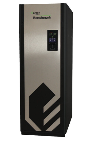
AERCO International Boiler Benchmark 1500
Need answers fast?
Explore the manual using AI.

Turn manuals into instant answers
with your AI-powered assistantTurn manuals into instant answers
with your AI-powered assistant
Complete asset maintenance, one click away
Get instant access to all the maintenance information you need. Empower technicians to perform preventive maintenance with asset packages, ready to use right out of the box.

Documents & Manuals
Find all the essential guides in one place.
 Tensioning Guide
- Belt-diagram
- C-120 pulleys
+ 13 more

Work Order Templates
Pre-built workflows to keep your asset running smoothly.
- Daily Electrical System Inspection
- Replace Roller and Pulley
- Install Engine B-120
+ 29 more

Procedures
Integrate maintenance plans directly into your work orders.
- Motion Industries
- Applied Industrial Technologies
- Electrical Brothers
+ 5 more

Parts
Access the parts list for your equipment in MaintainX.
- Drive Motor
- B2 Rollers
- Tensioning System
+ 40 more
AERCO International Boiler Benchmark 1500
Create an account to install this asset package.
Maintenance Plans for AERCO International Boiler Model Benchmark 1500
Integrate maintenance plans directly into your work orders in MaintainX.
1 Weekly Boiler Test
WARNING: Periodic testing of all boiler controls and safety devices is required to determine that they are operating as designed. Precautions shall be taken while tests are being performed to protect against bodily injury and property damage. The owner or user of an automatic boiler system should set up a formal system of periodic preventive maintenance and testing. Tests should be conducted on a regular basis and the results recorded in a log-book.
Instrument and equipment settings: Verify factory settings
Spark Igniter-Injector:
1. Set the ON/OFF switch on the control panel, to the OFF position. Disconnect AC power from the unit
2. Remove the top shroud from the unit by grasping the top handle and lifting straight up. This will disengage the shroud from the four (4) pins in the side panels.
3. Disconnect the cable from the igniter-injector (Figure 7-1).
4. Refer to the partial exploded view in Figure 7-2. Using a 7/16” open-end wrench, disconnect the compression nut securing the gas injector tube of the igniter-injector to the elbow of the staged ignition assembly. Disconnect the staged ignition assembly from the igniter-injector.
5. Next, loosen and remove the igniter-injector from the burner plate using a 1" open-end wrench.
6. Check the igniter-injector for evidence of erosion or carbon build-up. If there is evidence of substantial erosion or carbon build-up, the igniter-injector should be replaced. If carbon build-up is present, clean the component using fine emery cloth. Repeated carbon buildup is an indication that the combustion settings of the unit should be checked. Refer to Chapter 4 for combustion calibration procedures.

High Gas Pressure Test
Close the leak detection ball valve located at the high gas pressure switch
Upload a photo of the closed leak detection ball valve
Remove the 1/4“ plug from the leak detection ball valve
Upload a photo of the removed 1/4“ plug
Install a 0 – 16” W.C. manometer (or W.C. gauge) where the 1/4” plug was removed
Upload a photo of the installed manometer
Slowly open the leak detection ball valve
Start the unit in Manual mode at a valve position (firing rate) between 25 and 30%
Record the gas pressure reading on the manometer
6 Monthly O2 Sensor Maintenance
Warning: The O2 sensor may be hot. Allow the unit to cool sufficiently before starting the procedure.
Set the ON/OFF switch on the control panel to the OFF position and disconnect AC power from the unit.
Remove the top shroud from the unit by grasping the top handle and lifting straight up.
Disconnect the O2 sensor lead wire by pushing in on the release tab and pulling apart the connector.
Loosen and remove the O2 sensor and crush washer from the burner plate using a 15/16 open-end wrench.
Inspect the O2 sensor. If eroded, the sensor should be replaced. Otherwise clean the sensor with a fine emery cloth.
Reinstall the O2 sensor and crush washer on the burner plate.
Reconnect the sensor lead wire.
Reinstall the shroud on the unit.
Purge Switch Open During Purge Test
Warning: This procedure requires trained personnel!
Is the unit's ON/OFF switch in the OFF position?
Set the unit in manual mode and set the valve position
Air/Fuel Valve cover removed by rotating counterclockwise?
One of the two wires (#171 or #172) removed from the Purge Switch?
Unit start sequence initiated?
Did the unit shut down and display PRG SWITCH OPEN DURING PURGE?
Wire replaced on the Purge Switch and CLEAR button depressed?
Did the unit restart?
Remote Interlock Test
Warning: This procedure requires trained personnel!
Cover removed from the I/O Box
Unit started in Manual Mode
Set valve position between 25% and 30%
Jumper across the REMOTE INTL’K IN terminals removed
Unit shut down and displayed INTERLOCK OPEN
Interlock connection reconnected
INTERLOCK OPEN message cleared and unit restarted
Sign off on the Remote Interlock Test
Parts for AERCO International Boiler Benchmark 1500
Access the parts list for your equipment in MaintainX.
Condensate Drain Trap
24060
Maintenance Kit
58025-01
Waterside/Fireside Inspection Kit
58025-13
Igniter-Injector
66013
Flame Detector
66020
Condensate Drain Trap
24060
Maintenance Kit
58025-01
Waterside/Fireside Inspection Kit
58025-13
Igniter-Injector
66013
Flame Detector
66020
Condensate Drain Trap
24060
Maintenance Kit
58025-01
Waterside/Fireside Inspection Kit
58025-13
Igniter-Injector
66013
Flame Detector
66020
Unlock efficiency
with MaintainX CoPilot
MaintainX CoPilot is your expert colleague, on call 24/7, helping your team find the answers they need to keep equipment running.
Reduce Unplanned Downtime
Ensure your team follows consistent procedures to minimize equipment failures and costly delays.
Maximize Asset Availability
Keep your assets running longer and more reliably, with standardized maintenance workflows from OEM manuals.
Lower Maintenance Costs
Turn any technician into an expert to streamline operations, maintain more assets, and reduce overall costs.
Thousands of companies manage their assets with MaintainX

'%3e%3cpath%20fill='url(%23b)'%20d='M66.008%2080.068c-5.084-.786-9.763-3.834-12.442-8.68a16.942%2016.942%200%200%201-1.87-5.18c1.096.19%202.203.476%203.298.87%206.525%202.333%2010.836%207.68%2011.014%2012.99ZM51.47%2061.576c.488-5.524%203.62-10.716%208.847-13.597a17.132%2017.132%200%200%201%2011.335-1.882c-.798%208.145-7.43%2014.848-16.038%2015.599-1.417.119-2.799.07-4.144-.12Zm28.564-11.478a17.513%2017.513%200%200%201%203.727%204.62c4.608%208.335%201.584%2018.813-6.75%2023.409a16.988%2016.988%200%200%201-4.359%201.679%2019.624%2019.624%200%200%201-3.977-12.776c.346-7.561%204.942-13.931%2011.36-16.932Z'/%3e%3cpath%20fill='%23110F0D'%20fill-rule='evenodd'%20d='M142.831%2048.324h4.977V77.03h-4.977V48.324Zm27.278%2013.002c.322%201.048.453%202.263.453%203.62v12.073h-4.787V66.208c0-.75-.047-1.572-.154-2.143-.453-2.382-1.822-3.572-4.215-3.572-2.31%200-3.882%201.274-4.43%203.476-.143.596-.226%201.405-.226%202.25v10.8h-4.787V56.623h4.477v2.989c1.536-2.5%203.906-3.43%206.371-3.43%203.488%200%206.263%201.68%207.298%205.144Zm24.636%207.323c0%203.882-2.358%206.525-5.763%207.727-1.298.453-2.632.643-4.62.643h-10.169V48.324h9.085c1.691%200%203.156.143%204.049.38%203.465.93%205.727%203.68%205.727%207.335%200%202.441-.81%204.156-2.762%205.644%202.905%201.417%204.453%203.727%204.453%206.966Zm-15.634-8.656h4.584c1.024%200%201.917-.143%202.536-.417%201.215-.548%201.905-1.608%201.905-3.167%200-1.548-.643-2.572-1.845-3.132-.691-.31-1.762-.452-2.763-.452h-4.417v7.168Zm10.716%208.465c0-1.536-.893-3.37-3.227-3.893-.428-.095-1.036-.143-1.571-.143h-5.918v8.085h5.501c.56%200%201.429-.048%201.953-.167%201.94-.453%203.262-1.846%203.262-3.882Zm47.747-11.847-8.097%2020.408h-4.429l-8.109-20.408h5.191l5.192%2014.574%205.108-14.574h5.144Zm-20.218%2010.002c0%20.69-.036%201.262-.155%201.94h-15.943c.631%202.87%202.714%204.728%205.882%204.728%202.131%200%203.607-.882%204.703-2.525h4.87c-1.762%204.144-5.204%206.692-9.657%206.692-6.084%200-10.537-4.858-10.537-10.49%200-6.108%204.524-10.776%2010.335-10.776%206.239%200%2010.442%204.954%2010.502%2010.43Zm-4.763-1.405c-.333-2.846-2.643-4.858-5.691-4.858-2.894%200-5.287%201.929-5.621%204.858h11.312Zm-72.667%203.44c0%204.787-3.287%208.371-9.419%208.371H119.363V64.66c-1.917.274-3.87.69-5.811%201.238l4.537%2011.121h-5.418l-3.596-9.585c-5.144%202.084-10.085%205.216-14.217%209.585h-4.786L101.8%2048.312h4.56l5.68%2013.883a44.112%2044.112%200%200%201%207.323-1.774V48.312h9.084c1.703%200%203.156.143%204.061.393%203.453.929%205.727%203.667%205.727%207.323%200%201.917-.738%204.179-2.81%205.691%203.06%201.56%204.501%204.025%204.501%206.93Zm-15.634-8.667a62.664%2062.664%200%200%201%202.06-.036c1.703.012%203.239.131%204.608.37%201.441-.549%202.357-1.727%202.357-3.537%200-1.941-.881-3.144-2.488-3.667-.548-.18-1.358-.286-2.322-.286h-4.215v7.156Zm-16.55%203.905-3.715-9.894-6.394%2016.502c2.833-2.595%206.263-4.858%2010.109-6.608Zm27.254%204.74c0-2.775-3.131-4.347-8.513-4.418-.715%200-1.441.011-2.191.047v8.252h5.918c2.548%200%204.786-1.37%204.786-3.882Z'%20clip-rule='evenodd'/%3e%3c/g%3e%3cdefs%3e%3clinearGradient%20id='b'%20x1='51.47'%20x2='85.916'%20y1='62.946'%20y2='62.946'%20gradientUnits='userSpaceOnUse'%3e%3cstop%20stop-color='%23CD9F28'/%3e%3cstop%20offset='1'%20stop-color='%23ECD80B'/%3e%3c/linearGradient%3e%3cclipPath%20id='a'%3e%3cpath%20fill='%23fff'%20d='M51.47%2045.728h186.104V80.14H51.47z'/%3e%3c/clipPath%3e%3c/defs%3e%3c/svg%3e)


More from AERCO International
Explore Other Assets


© 2026 MaintainX. All rights reserved.