


Unibloc Lobe Pump 4551AF1-10-10AF30H-82-30B-12a-V
Need answers fast?
Explore the manual using AI.
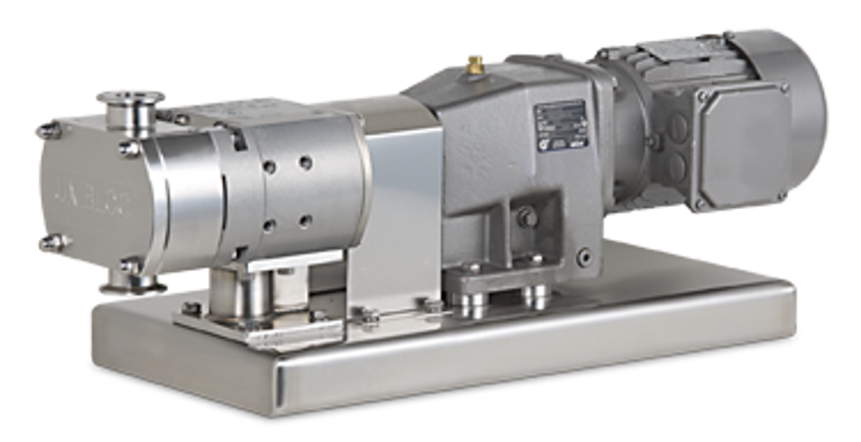
The Unibloc Lobe Pump 4551AF1-10-10AF30H-82-30B-12a-V is a high-performance industrial pump designed for efficient fluid transfer. Known for its reliability and versatility, this OEM lobe pump is ideal for various applications, ensuring optimal flow rates and minimal maintenance requirements.
Turn manuals into instant answers
with your AI-powered assistantTurn manuals into instant answers
with your AI-powered assistant
Manual for Unibloc Lobe Pump 4551AF1-10-10AF30H-82-30B-12a-V
Complete asset maintenance, one click away
Get instant access to all the maintenance information you need. Empower technicians to perform preventive maintenance with asset packages, ready to use right out of the box.

Documents & Manuals
Find all the essential guides in one place.
 Tensioning Guide
- Belt-diagram
- C-120 pulleys
+ 13 more

Work Order Templates
Pre-built workflows to keep your asset running smoothly.
- Daily Electrical System Inspection
- Replace Roller and Pulley
- Install Engine B-120
+ 29 more

Procedures
Integrate maintenance plans directly into your work orders.
- Motion Industries
- Applied Industrial Technologies
- Electrical Brothers
+ 5 more

Parts
Access the parts list for your equipment in MaintainX.
- Drive Motor
- B2 Rollers
- Tensioning System
+ 40 more
Unibloc Lobe Pump 4551AF1-10-10AF30H-82-30B-12a-V
Create an account to install this asset package.
Maintenance Plans for Unibloc Lobe Pump Model 4551AF1-10-10AF30H-82-30B-12a-V
Integrate maintenance plans directly into your work orders in MaintainX.
Shaft Seal and Rotor Maintenance
Step 1: Preparation for Shaft Seal Removal
Reference: Figure 3.0, Items 1, 2, 3a, 3b, 14a, 14b, 16
1. Disengage Power
Shut down and disconnect the hydraulic or PTO drive.
Ensure all energy sources are locked out.
2. Depressurize and Disconnect
Close suction and discharge valves.
Depressurize the pump and remove it from the system if necessary.
3. Remove the Front Cover

Gearbox Maintenance
4.0 Gearbox Maintenance and Service
1. Disconnect power and disengage hydraulic or PTO motor before servicing.
2. Depressurize system and close valves on suction and discharge sides.
3. Disconnect piping and remove the pump from the system.
4. If flange-mounted to motor, remove four bolts (9) and unmount the pump.
5. Remove the wet end components (cover, rotors, housing, shaft seals) before gearbox disassembly.
4.1 Gearbox Disassembly
Reference: Figure 4.1 (Items 7, 8, 10, 11a, 12, 13, 21, 23)
1. Drain oil by removing drain plug or cover (7).
Relief Valve Maintenance
6.0 Relief Valve Cover Settings and Maintenance
1. UNIBLOC pumps may come with relief valve covers to prevent over-pressurizing the pump.
2. Cover 3237 works in one direction and must have discharge side at inlet.
3. Cover 3239B works in both directions and adjusts pressure via spring compression.
4. Adjustments must be made while pump is running at desired flow rate.
5. Use caution when handling hot pumps or valves — wear protective gear.
6.1 Setting the Relief Valve Cover
6.1.1 Setting Relief Valve Cover: P/N 3237
1. Unscrew housing (10) to expose adjusting mechanism.
Parts for Unibloc Lobe Pump 4551AF1-10-10AF30H-82-30B-12a-V
Access the parts list for your equipment in MaintainX.
Spring Housing
3237-6
Rotor Housing Cover
3237-1L
1/2" NPT Vent
RV0..5
O-Ring
4802
M12x40 (Hex) CharLynn Motor Bolt
HBM12X40
Spring Housing
3237-6
Rotor Housing Cover
3237-1L
1/2" NPT Vent
RV0..5
O-Ring
4802
M12x40 (Hex) CharLynn Motor Bolt
HBM12X40
Spring Housing
3237-6
Rotor Housing Cover
3237-1L
1/2" NPT Vent
RV0..5
O-Ring
4802
M12x40 (Hex) CharLynn Motor Bolt
HBM12X40
Unlock efficiency
with MaintainX CoPilot
MaintainX CoPilot is your expert colleague, on call 24/7, helping your team find the answers they need to keep equipment running.
Reduce Unplanned Downtime
Ensure your team follows consistent procedures to minimize equipment failures and costly delays.
Maximize Asset Availability
Keep your assets running longer and more reliably, with standardized maintenance workflows from OEM manuals.
Lower Maintenance Costs
Turn any technician into an expert to streamline operations, maintain more assets, and reduce overall costs.
Thousands of companies manage their assets with MaintainX

'%3e%3cpath%20fill='url(%23b)'%20d='M66.008%2080.068c-5.084-.786-9.763-3.834-12.442-8.68a16.942%2016.942%200%200%201-1.87-5.18c1.096.19%202.203.476%203.298.87%206.525%202.333%2010.836%207.68%2011.014%2012.99ZM51.47%2061.576c.488-5.524%203.62-10.716%208.847-13.597a17.132%2017.132%200%200%201%2011.335-1.882c-.798%208.145-7.43%2014.848-16.038%2015.599-1.417.119-2.799.07-4.144-.12Zm28.564-11.478a17.513%2017.513%200%200%201%203.727%204.62c4.608%208.335%201.584%2018.813-6.75%2023.409a16.988%2016.988%200%200%201-4.359%201.679%2019.624%2019.624%200%200%201-3.977-12.776c.346-7.561%204.942-13.931%2011.36-16.932Z'/%3e%3cpath%20fill='%23110F0D'%20fill-rule='evenodd'%20d='M142.831%2048.324h4.977V77.03h-4.977V48.324Zm27.278%2013.002c.322%201.048.453%202.263.453%203.62v12.073h-4.787V66.208c0-.75-.047-1.572-.154-2.143-.453-2.382-1.822-3.572-4.215-3.572-2.31%200-3.882%201.274-4.43%203.476-.143.596-.226%201.405-.226%202.25v10.8h-4.787V56.623h4.477v2.989c1.536-2.5%203.906-3.43%206.371-3.43%203.488%200%206.263%201.68%207.298%205.144Zm24.636%207.323c0%203.882-2.358%206.525-5.763%207.727-1.298.453-2.632.643-4.62.643h-10.169V48.324h9.085c1.691%200%203.156.143%204.049.38%203.465.93%205.727%203.68%205.727%207.335%200%202.441-.81%204.156-2.762%205.644%202.905%201.417%204.453%203.727%204.453%206.966Zm-15.634-8.656h4.584c1.024%200%201.917-.143%202.536-.417%201.215-.548%201.905-1.608%201.905-3.167%200-1.548-.643-2.572-1.845-3.132-.691-.31-1.762-.452-2.763-.452h-4.417v7.168Zm10.716%208.465c0-1.536-.893-3.37-3.227-3.893-.428-.095-1.036-.143-1.571-.143h-5.918v8.085h5.501c.56%200%201.429-.048%201.953-.167%201.94-.453%203.262-1.846%203.262-3.882Zm47.747-11.847-8.097%2020.408h-4.429l-8.109-20.408h5.191l5.192%2014.574%205.108-14.574h5.144Zm-20.218%2010.002c0%20.69-.036%201.262-.155%201.94h-15.943c.631%202.87%202.714%204.728%205.882%204.728%202.131%200%203.607-.882%204.703-2.525h4.87c-1.762%204.144-5.204%206.692-9.657%206.692-6.084%200-10.537-4.858-10.537-10.49%200-6.108%204.524-10.776%2010.335-10.776%206.239%200%2010.442%204.954%2010.502%2010.43Zm-4.763-1.405c-.333-2.846-2.643-4.858-5.691-4.858-2.894%200-5.287%201.929-5.621%204.858h11.312Zm-72.667%203.44c0%204.787-3.287%208.371-9.419%208.371H119.363V64.66c-1.917.274-3.87.69-5.811%201.238l4.537%2011.121h-5.418l-3.596-9.585c-5.144%202.084-10.085%205.216-14.217%209.585h-4.786L101.8%2048.312h4.56l5.68%2013.883a44.112%2044.112%200%200%201%207.323-1.774V48.312h9.084c1.703%200%203.156.143%204.061.393%203.453.929%205.727%203.667%205.727%207.323%200%201.917-.738%204.179-2.81%205.691%203.06%201.56%204.501%204.025%204.501%206.93Zm-15.634-8.667a62.664%2062.664%200%200%201%202.06-.036c1.703.012%203.239.131%204.608.37%201.441-.549%202.357-1.727%202.357-3.537%200-1.941-.881-3.144-2.488-3.667-.548-.18-1.358-.286-2.322-.286h-4.215v7.156Zm-16.55%203.905-3.715-9.894-6.394%2016.502c2.833-2.595%206.263-4.858%2010.109-6.608Zm27.254%204.74c0-2.775-3.131-4.347-8.513-4.418-.715%200-1.441.011-2.191.047v8.252h5.918c2.548%200%204.786-1.37%204.786-3.882Z'%20clip-rule='evenodd'/%3e%3c/g%3e%3cdefs%3e%3clinearGradient%20id='b'%20x1='51.47'%20x2='85.916'%20y1='62.946'%20y2='62.946'%20gradientUnits='userSpaceOnUse'%3e%3cstop%20stop-color='%23CD9F28'/%3e%3cstop%20offset='1'%20stop-color='%23ECD80B'/%3e%3c/linearGradient%3e%3cclipPath%20id='a'%3e%3cpath%20fill='%23fff'%20d='M51.47%2045.728h186.104V80.14H51.47z'/%3e%3c/clipPath%3e%3c/defs%3e%3c/svg%3e)


Explore Other Assets


© 2026 MaintainX. All rights reserved.