


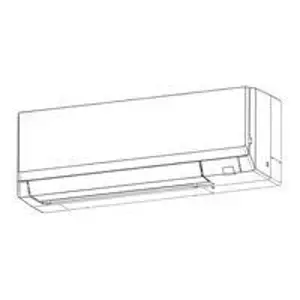
Mitsubishi Indoor Unit TPKFYP006LM140A
Need answers fast?
Explore the manual using AI.

Turn manuals into instant answers
with your AI-powered assistantTurn manuals into instant answers
with your AI-powered assistant
Manual for Mitsubishi Indoor Unit TPKFYP006LM140A
Complete asset maintenance, one click away
Get instant access to all the maintenance information you need. Empower technicians to perform preventive maintenance with asset packages, ready to use right out of the box.

Documents & Manuals
Find all the essential guides in one place.
 Tensioning Guide
- Belt-diagram
- C-120 pulleys
+ 13 more

Work Order Templates
Pre-built workflows to keep your asset running smoothly.
- Daily Electrical System Inspection
- Replace Roller and Pulley
- Install Engine B-120
+ 29 more

Procedures
Integrate maintenance plans directly into your work orders.
- Motion Industries
- Applied Industrial Technologies
- Electrical Brothers
+ 5 more

Parts
Access the parts list for your equipment in MaintainX.
- Drive Motor
- B2 Rollers
- Tensioning System
+ 40 more
Mitsubishi Indoor Unit TPKFYP006LM140A
Create an account to install this asset package.
Maintenance Plans for Mitsubishi Indoor Unit Model TPKFYP006LM140A
Integrate maintenance plans directly into your work orders in MaintainX.
Indoor Unit Vane Motor Replacement
Remove the nozzle assembly
Remove 2 screws of the vane motor unit cover, and pull out the vane motor unit
Remove screw of the vane motor (LOWER)
Remove the vane motor (LOWER) from the vane motor unit cover
Disconnect the connector (white) from the vane motor (LOWER)
Remove 2 screw of the vane motor (UPPER)
Remove the vane motor (UPPER) from the vane motor unit cover
Disconnect the connector (blue) from the vane motor (UPPER)
Upload a photo of the replaced vane motor

Indoor Unit Refrigirant Charging
Cautions for service
Refrigerant recovered from the unit completely
Refrigerant not released in the air
Cycle charged with specified amount of refrigerant after service
Filter drier installed for service
Filter drier used for new refrigerant
Additional refrigerant charge
Cylinder for R410A is a syphon type
Charging performed with the cylinder of syphon stood vertically
Indoor Unit Panel Replacement
Warning: Ensure the unit is powered off before starting the procedure.
Insert the driver to the hole at VANE LOWER shaft and slide the VANE LOWER shaft (2 places each). Push VANE UPPER shaft with the driver.
Pull the VANE LOWER and VANE UPPER from unit.
Remove 2 screw caps of the front panel. Remove 2 screws.
Upload a photo of the removed screws
Hold the lower part of both ends of the front panel and pull it slightly toward you, and then remove the front panel by pushing it upward.
Remove the screw of the corner box.
Upload a photo of the removed corner box screw
Remove the corner box.
Indoor Unit Room Temperature Thermistor Replacement
Remove the panel and corner box
Remove the electrical box covers
Remove the room temperature thermistor
Disconnect the connector (CN20) on the indoor controller board
Indoor Unit Adress/Controller/Wireless/Led Board Replacement
Remove the panel and the corner box
Remove the front and side electrical box covers (each 2 screw)
Disconnect the connectors of address board
Disconnect the connectors on the indoor controller board
Remove the switch board holder and open the cover
Pull out the indoor controller board toward you then remove the indoor controller board and switch board
Remove the holder of wireless remote controller board and LED board
Disconnect the connector of wireless remote controller board and LED board
Remove the wireless remote controller board and LED board from the holder
Parts for Mitsubishi Indoor Unit TPKFYP006LM140A
Access the parts list for your equipment in MaintainX.
Drain Pump Kit
PAC-SK01DM-E
Drain Pump Kit
PAC-SK01DM-E
Drain Pump Kit
PAC-SK01DM-E
Unlock efficiency
with MaintainX CoPilot
MaintainX CoPilot is your expert colleague, on call 24/7, helping your team find the answers they need to keep equipment running.
Reduce Unplanned Downtime
Ensure your team follows consistent procedures to minimize equipment failures and costly delays.
Maximize Asset Availability
Keep your assets running longer and more reliably, with standardized maintenance workflows from OEM manuals.
Lower Maintenance Costs
Turn any technician into an expert to streamline operations, maintain more assets, and reduce overall costs.
Thousands of companies manage their assets with MaintainX

'%3e%3cpath%20fill='url(%23b)'%20d='M66.008%2080.068c-5.084-.786-9.763-3.834-12.442-8.68a16.942%2016.942%200%200%201-1.87-5.18c1.096.19%202.203.476%203.298.87%206.525%202.333%2010.836%207.68%2011.014%2012.99ZM51.47%2061.576c.488-5.524%203.62-10.716%208.847-13.597a17.132%2017.132%200%200%201%2011.335-1.882c-.798%208.145-7.43%2014.848-16.038%2015.599-1.417.119-2.799.07-4.144-.12Zm28.564-11.478a17.513%2017.513%200%200%201%203.727%204.62c4.608%208.335%201.584%2018.813-6.75%2023.409a16.988%2016.988%200%200%201-4.359%201.679%2019.624%2019.624%200%200%201-3.977-12.776c.346-7.561%204.942-13.931%2011.36-16.932Z'/%3e%3cpath%20fill='%23110F0D'%20fill-rule='evenodd'%20d='M142.831%2048.324h4.977V77.03h-4.977V48.324Zm27.278%2013.002c.322%201.048.453%202.263.453%203.62v12.073h-4.787V66.208c0-.75-.047-1.572-.154-2.143-.453-2.382-1.822-3.572-4.215-3.572-2.31%200-3.882%201.274-4.43%203.476-.143.596-.226%201.405-.226%202.25v10.8h-4.787V56.623h4.477v2.989c1.536-2.5%203.906-3.43%206.371-3.43%203.488%200%206.263%201.68%207.298%205.144Zm24.636%207.323c0%203.882-2.358%206.525-5.763%207.727-1.298.453-2.632.643-4.62.643h-10.169V48.324h9.085c1.691%200%203.156.143%204.049.38%203.465.93%205.727%203.68%205.727%207.335%200%202.441-.81%204.156-2.762%205.644%202.905%201.417%204.453%203.727%204.453%206.966Zm-15.634-8.656h4.584c1.024%200%201.917-.143%202.536-.417%201.215-.548%201.905-1.608%201.905-3.167%200-1.548-.643-2.572-1.845-3.132-.691-.31-1.762-.452-2.763-.452h-4.417v7.168Zm10.716%208.465c0-1.536-.893-3.37-3.227-3.893-.428-.095-1.036-.143-1.571-.143h-5.918v8.085h5.501c.56%200%201.429-.048%201.953-.167%201.94-.453%203.262-1.846%203.262-3.882Zm47.747-11.847-8.097%2020.408h-4.429l-8.109-20.408h5.191l5.192%2014.574%205.108-14.574h5.144Zm-20.218%2010.002c0%20.69-.036%201.262-.155%201.94h-15.943c.631%202.87%202.714%204.728%205.882%204.728%202.131%200%203.607-.882%204.703-2.525h4.87c-1.762%204.144-5.204%206.692-9.657%206.692-6.084%200-10.537-4.858-10.537-10.49%200-6.108%204.524-10.776%2010.335-10.776%206.239%200%2010.442%204.954%2010.502%2010.43Zm-4.763-1.405c-.333-2.846-2.643-4.858-5.691-4.858-2.894%200-5.287%201.929-5.621%204.858h11.312Zm-72.667%203.44c0%204.787-3.287%208.371-9.419%208.371H119.363V64.66c-1.917.274-3.87.69-5.811%201.238l4.537%2011.121h-5.418l-3.596-9.585c-5.144%202.084-10.085%205.216-14.217%209.585h-4.786L101.8%2048.312h4.56l5.68%2013.883a44.112%2044.112%200%200%201%207.323-1.774V48.312h9.084c1.703%200%203.156.143%204.061.393%203.453.929%205.727%203.667%205.727%207.323%200%201.917-.738%204.179-2.81%205.691%203.06%201.56%204.501%204.025%204.501%206.93Zm-15.634-8.667a62.664%2062.664%200%200%201%202.06-.036c1.703.012%203.239.131%204.608.37%201.441-.549%202.357-1.727%202.357-3.537%200-1.941-.881-3.144-2.488-3.667-.548-.18-1.358-.286-2.322-.286h-4.215v7.156Zm-16.55%203.905-3.715-9.894-6.394%2016.502c2.833-2.595%206.263-4.858%2010.109-6.608Zm27.254%204.74c0-2.775-3.131-4.347-8.513-4.418-.715%200-1.441.011-2.191.047v8.252h5.918c2.548%200%204.786-1.37%204.786-3.882Z'%20clip-rule='evenodd'/%3e%3c/g%3e%3cdefs%3e%3clinearGradient%20id='b'%20x1='51.47'%20x2='85.916'%20y1='62.946'%20y2='62.946'%20gradientUnits='userSpaceOnUse'%3e%3cstop%20stop-color='%23CD9F28'/%3e%3cstop%20offset='1'%20stop-color='%23ECD80B'/%3e%3c/linearGradient%3e%3cclipPath%20id='a'%3e%3cpath%20fill='%23fff'%20d='M51.47%2045.728h186.104V80.14H51.47z'/%3e%3c/clipPath%3e%3c/defs%3e%3c/svg%3e)


More from Mitsubishi


Explore Other Assets


© 2026 MaintainX. All rights reserved.