


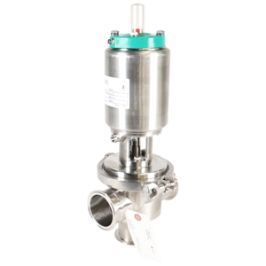
Alfa Laval Rotary Lobe Displacement Pump GHPD-532
Need answers fast?
Explore the manual using AI.
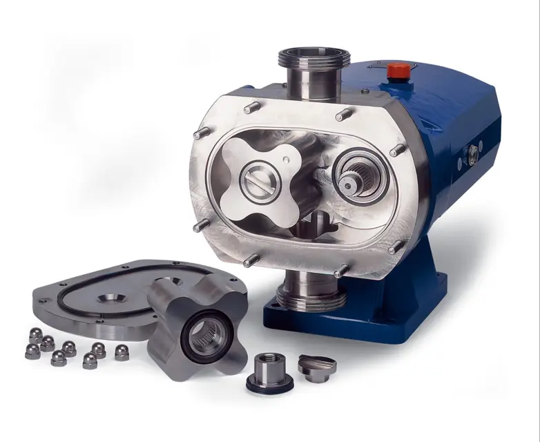
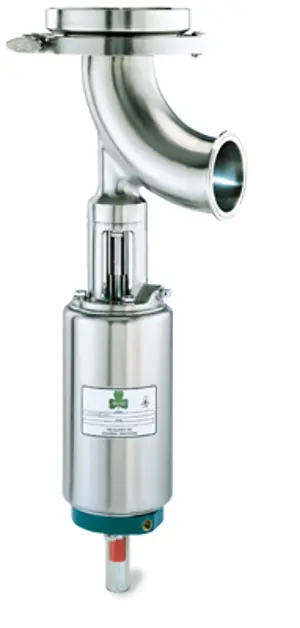
The Alfa Laval Rotary Lobe Displacement Pump GHPD-532 is designed for efficient fluid transfer in various industrial applications. Known for its reliability and performance, this pump excels in handling viscous fluids while minimizing shear and maintaining product integrity. Optimize your operations with this robust asset from Alfa Laval.
Turn manuals into instant answers
with your AI-powered assistantTurn manuals into instant answers
with your AI-powered assistant
Manual for Alfa Laval Rotary Lobe Displacement Pump GHPD-532
Complete asset maintenance, one click away
Get instant access to all the maintenance information you need. Empower technicians to perform preventive maintenance with asset packages, ready to use right out of the box.

Documents & Manuals
Find all the essential guides in one place.
 Tensioning Guide
- Belt-diagram
- C-120 pulleys
+ 13 more

Work Order Templates
Pre-built workflows to keep your asset running smoothly.
- Daily Electrical System Inspection
- Replace Roller and Pulley
- Install Engine B-120
+ 29 more

Procedures
Integrate maintenance plans directly into your work orders.
- Motion Industries
- Applied Industrial Technologies
- Electrical Brothers
+ 5 more

Parts
Access the parts list for your equipment in MaintainX.
- Drive Motor
- B2 Rollers
- Tensioning System
+ 40 more
Alfa Laval Rotary Lobe Displacement Pump GHPD-532
Create an account to install this asset package.
Maintenance Plans for Alfa Laval Rotary Lobe Displacement Pump Model GHPD-532
Integrate maintenance plans directly into your work orders in MaintainX.
2 Yearly Grease Replacement
1. Pump supplied grease filled.
2. Change - every two years (dusty air conditions)
* Change - every six years (clean air conditions)
3. Fill with grease by pumping grease into the rear of the gearcase.;

3000 Hourly Lubrication Oil Replacement
1. The pump will NOT be supplied oil filled.
2. First change - After 150 hours of operation.
3. Fill with oil through the filler plug to the level indicated in the sight glass.;
1 Weekly Pump Maintenance
1. Checking the oil level in the gearcase (if applicable).
2. Checking the mechanical seals for leakage and replacing as necessary.
3. Adjusting the packed glands to control leakage.
4. Checking the oil seals for leakage.
5. Check pumping pressures.;
Packed Gland with Flush Adjustment
CAUTION! DRIP LEAKAGE IS ESSENTIAL TO PREVENT OVER HEATING OF THE GLAND AREA WHICH WILL CAUSE SEAL FAILURE.
IMPORTANT! Stop and remove gland guard for checking temperature of housing and observing leakage. ALWAYS REPLACE THE GUARD BEFORE RESTARTING.
1. Lightly tighten up the gland follower.
2. Flood the pumphead and determine if the gland leakage is acceptable. Tighten the gland follower nuts until an acceptable leakage is achieved.
3. Start the pump and allow to run for 10 minutes. If the gland becomes significantly hotter than other parts of the pump, the gland is too tight.
4. Stop the pump and allow it to cool then repeat the above until the gland temperature is stable and gland slightly weeping.
5. Run the pump at 10 minute intervals tightening the gland follower nuts by a ½ of a turn until the leak is at an acceptable rate.;
O-Ring Seal Replacement
– The large 'O' ring sits within the rotorcase bore and runs on the shaft sleeve. Rotation for the shaft sleeve is provided by a spring which locates in a slot on the shaft. An 'O' ring seals the shaft sleeve to the shaft.
REMOVING THE 'O' RING SEAL
1. Remove the rotorcase.
2. Slide the shaft sleeve from the shaft and inspect the 'O' rings.
FITTING THE 'O' RING SEAL
1. Lightly lubricate the 'O' rings with greas (food quality if necessary), locate in the shat sleeve and rotorcase bore.
2. Slide the shaft sleeve onto the shaft an locate the pin into the slot on the shaft.;
Unlock efficiency
with MaintainX CoPilot
MaintainX CoPilot is your expert colleague, on call 24/7, helping your team find the answers they need to keep equipment running.
Reduce Unplanned Downtime
Ensure your team follows consistent procedures to minimize equipment failures and costly delays.
Maximize Asset Availability
Keep your assets running longer and more reliably, with standardized maintenance workflows from OEM manuals.
Lower Maintenance Costs
Turn any technician into an expert to streamline operations, maintain more assets, and reduce overall costs.
Thousands of companies manage their assets with MaintainX

'%3e%3cpath%20fill='url(%23b)'%20d='M66.008%2080.068c-5.084-.786-9.763-3.834-12.442-8.68a16.942%2016.942%200%200%201-1.87-5.18c1.096.19%202.203.476%203.298.87%206.525%202.333%2010.836%207.68%2011.014%2012.99ZM51.47%2061.576c.488-5.524%203.62-10.716%208.847-13.597a17.132%2017.132%200%200%201%2011.335-1.882c-.798%208.145-7.43%2014.848-16.038%2015.599-1.417.119-2.799.07-4.144-.12Zm28.564-11.478a17.513%2017.513%200%200%201%203.727%204.62c4.608%208.335%201.584%2018.813-6.75%2023.409a16.988%2016.988%200%200%201-4.359%201.679%2019.624%2019.624%200%200%201-3.977-12.776c.346-7.561%204.942-13.931%2011.36-16.932Z'/%3e%3cpath%20fill='%23110F0D'%20fill-rule='evenodd'%20d='M142.831%2048.324h4.977V77.03h-4.977V48.324Zm27.278%2013.002c.322%201.048.453%202.263.453%203.62v12.073h-4.787V66.208c0-.75-.047-1.572-.154-2.143-.453-2.382-1.822-3.572-4.215-3.572-2.31%200-3.882%201.274-4.43%203.476-.143.596-.226%201.405-.226%202.25v10.8h-4.787V56.623h4.477v2.989c1.536-2.5%203.906-3.43%206.371-3.43%203.488%200%206.263%201.68%207.298%205.144Zm24.636%207.323c0%203.882-2.358%206.525-5.763%207.727-1.298.453-2.632.643-4.62.643h-10.169V48.324h9.085c1.691%200%203.156.143%204.049.38%203.465.93%205.727%203.68%205.727%207.335%200%202.441-.81%204.156-2.762%205.644%202.905%201.417%204.453%203.727%204.453%206.966Zm-15.634-8.656h4.584c1.024%200%201.917-.143%202.536-.417%201.215-.548%201.905-1.608%201.905-3.167%200-1.548-.643-2.572-1.845-3.132-.691-.31-1.762-.452-2.763-.452h-4.417v7.168Zm10.716%208.465c0-1.536-.893-3.37-3.227-3.893-.428-.095-1.036-.143-1.571-.143h-5.918v8.085h5.501c.56%200%201.429-.048%201.953-.167%201.94-.453%203.262-1.846%203.262-3.882Zm47.747-11.847-8.097%2020.408h-4.429l-8.109-20.408h5.191l5.192%2014.574%205.108-14.574h5.144Zm-20.218%2010.002c0%20.69-.036%201.262-.155%201.94h-15.943c.631%202.87%202.714%204.728%205.882%204.728%202.131%200%203.607-.882%204.703-2.525h4.87c-1.762%204.144-5.204%206.692-9.657%206.692-6.084%200-10.537-4.858-10.537-10.49%200-6.108%204.524-10.776%2010.335-10.776%206.239%200%2010.442%204.954%2010.502%2010.43Zm-4.763-1.405c-.333-2.846-2.643-4.858-5.691-4.858-2.894%200-5.287%201.929-5.621%204.858h11.312Zm-72.667%203.44c0%204.787-3.287%208.371-9.419%208.371H119.363V64.66c-1.917.274-3.87.69-5.811%201.238l4.537%2011.121h-5.418l-3.596-9.585c-5.144%202.084-10.085%205.216-14.217%209.585h-4.786L101.8%2048.312h4.56l5.68%2013.883a44.112%2044.112%200%200%201%207.323-1.774V48.312h9.084c1.703%200%203.156.143%204.061.393%203.453.929%205.727%203.667%205.727%207.323%200%201.917-.738%204.179-2.81%205.691%203.06%201.56%204.501%204.025%204.501%206.93Zm-15.634-8.667a62.664%2062.664%200%200%201%202.06-.036c1.703.012%203.239.131%204.608.37%201.441-.549%202.357-1.727%202.357-3.537%200-1.941-.881-3.144-2.488-3.667-.548-.18-1.358-.286-2.322-.286h-4.215v7.156Zm-16.55%203.905-3.715-9.894-6.394%2016.502c2.833-2.595%206.263-4.858%2010.109-6.608Zm27.254%204.74c0-2.775-3.131-4.347-8.513-4.418-.715%200-1.441.011-2.191.047v8.252h5.918c2.548%200%204.786-1.37%204.786-3.882Z'%20clip-rule='evenodd'/%3e%3c/g%3e%3cdefs%3e%3clinearGradient%20id='b'%20x1='51.47'%20x2='85.916'%20y1='62.946'%20y2='62.946'%20gradientUnits='userSpaceOnUse'%3e%3cstop%20stop-color='%23CD9F28'/%3e%3cstop%20offset='1'%20stop-color='%23ECD80B'/%3e%3c/linearGradient%3e%3cclipPath%20id='a'%3e%3cpath%20fill='%23fff'%20d='M51.47%2045.728h186.104V80.14H51.47z'/%3e%3c/clipPath%3e%3c/defs%3e%3c/svg%3e)


More from Alfa Laval


Explore Other Assets


© 2026 MaintainX. All rights reserved.