


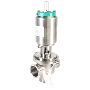
Alfa Laval Rotary Lobe Displacement Pump GHPD-432
Need answers fast?
Explore the manual using AI.
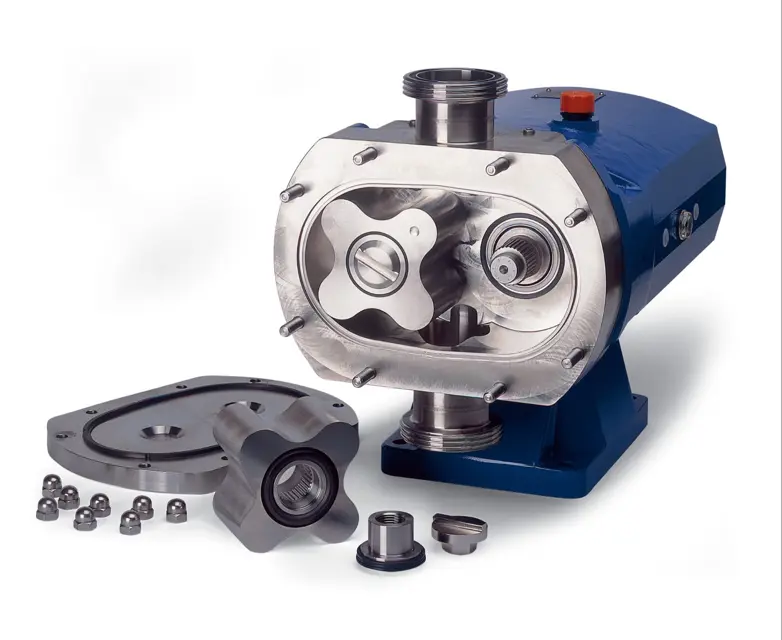
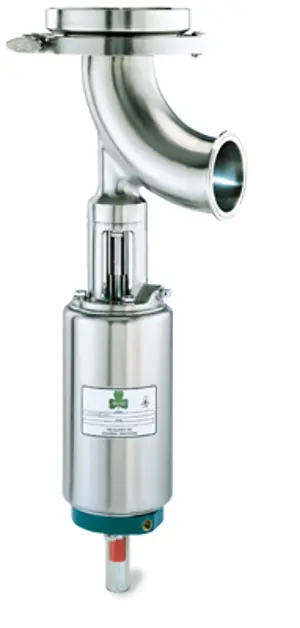
The Alfa Laval Rotary Lobe Displacement Pump GHPD-432 is a high-performance pump designed for efficient fluid transfer in various industrial applications. Known for its reliability and durability, this pump ensures optimal operation and minimal downtime, making it an essential asset in any processing facility.
Turn manuals into instant answers
with your AI-powered assistantTurn manuals into instant answers
with your AI-powered assistant
Manual for Alfa Laval Rotary Lobe Displacement Pump GHPD-432
Complete asset maintenance, one click away
Get instant access to all the maintenance information you need. Empower technicians to perform preventive maintenance with asset packages, ready to use right out of the box.

Documents & Manuals
Find all the essential guides in one place.
 Tensioning Guide
- Belt-diagram
- C-120 pulleys
+ 13 more

Work Order Templates
Pre-built workflows to keep your asset running smoothly.
- Daily Electrical System Inspection
- Replace Roller and Pulley
- Install Engine B-120
+ 29 more

Procedures
Integrate maintenance plans directly into your work orders.
- Motion Industries
- Applied Industrial Technologies
- Electrical Brothers
+ 5 more

Parts
Access the parts list for your equipment in MaintainX.
- Drive Motor
- B2 Rollers
- Tensioning System
+ 40 more
Alfa Laval Rotary Lobe Displacement Pump GHPD-432
Create an account to install this asset package.
Maintenance Plans for Alfa Laval Rotary Lobe Displacement Pump Model GHPD-432
Integrate maintenance plans directly into your work orders in MaintainX.
Double Hyclean Seal Replacement
1. Firmly press on the o-rings (15) to the rear stationary faces (14) and locate them within the rear flush housing (16,17).
2. Carefully fit the rear seal housings (16,17) with the stationary face onto the shaft (22). (Caution: do not chip stationary face).
3. Push outboard rotary assembly (10,11) onto pump shaft (22) to the setting dimension (A) indicated on the assembly drawing and tighten set screws.
4. Locate o-rings on the shaft (5, rotary) and within the rotorcase bore (1, stationary).
5. Press washer (7) underneath the inside drive pin into the rotary face (6) and gently slide onto the shaft, locating the pin in the shaft slot.
6. Position the wave spring (3) over the stationary face (2), push into the rotorcase.
7. Position front seal housing (9) onto rotorcase and hex head tighten screws (8). Be sure not to over tighten.
8. Refit the rotorcase, using the shaft sleeve to ensure stationary seal is not chipped during assembly.
9. Fit rear seal housings (16,17) and o-rings (12) to front flush housings (9) and tighten the hex nuts (18). (Caution: Be sure not to overtighten the hex nuts).;

3000 Hourly Lubrication Oil Replacement
1. The pump will NOT be supplied oil filled.
2. First change - After 150 hours of operation.
3. Fill with oil through the filler plug to the level indicated in the sight glass.;
Initial 150 Hours Lubrication Oil Replacement
1. The pump will NOT be supplied oil filled.
2. First change - After 150 hours of operation.
3. Only use the oil/grease types recommended by your supplier.
4. Fill with oil through the filler plug to the level indicated in the sight glass.;
Pump Cleaning
• The pump can be manually cleaned or cleaned in place (C.I.P.). The following is an example of a typical CIP procedure. However specific advice for each application should be sought from the pump supplier.
1. Flush through the system with cold water (42°F).
2. Run hot caustic soda (158-176°C) at 2.5% dilution through the system for 20-30 minutes.
3. Final flush through with cold water again.
NEVER touch the pump or pipes as they will be extremely HOT!
DO NOT subject the pump to rapid temperature changes during C.I.P. procedures, as pump seizure can result from thermal shock. A suitable by-pass is recommended.
ALWAYS use rubber gloves and protective when handling caustic agents.
ALWAYS rinse will with clean water using a cleaning agent.
ALWAYS store/discharge cleaning agents in accordance with current rules d/directives.;
Flushed Hyclean Seal Replacement
– The seal rotary face is driven by a pin which locates in a slot on the shaft. A washer is located between the shaft shoulder and rotary face. A seal between the rotary face and shaft is provided by an 'O' ring.
– The stationary face is prevented from rotating as it has a flat side which sits in the rotorcase bore. Face to face contact is provided by a wave spring.
– Axial movement of the stationary face is prevented by a retaining clip. An 'O' ring within the rotorcase bore provides a seal onto the stationary face.
– A seal housing encloses the hyclean seal and is seal by an 'O' ring and retained to the rotorcase by socket head cap screws. A lip seal sits within the seal housing and runs on the rotary face, thus providing a seal.
CAUTION! SEAL FACES ARE BRITTLE - TAKE EXTREME CARE WHEN HANDLING. REMOVING THE FLUSHED HYCLEAN SEAL
REMOVING THE FLUSHED HYCLEAN SEAL
1. Carefully support and remove the rotorcase with the seal housing and stationary face still attached.
2. Slide the rotary face from the shaft.
3. Remove the seal housing screws to inspect the seal.
Unlock efficiency
with MaintainX CoPilot
MaintainX CoPilot is your expert colleague, on call 24/7, helping your team find the answers they need to keep equipment running.
Reduce Unplanned Downtime
Ensure your team follows consistent procedures to minimize equipment failures and costly delays.
Maximize Asset Availability
Keep your assets running longer and more reliably, with standardized maintenance workflows from OEM manuals.
Lower Maintenance Costs
Turn any technician into an expert to streamline operations, maintain more assets, and reduce overall costs.
Thousands of companies manage their assets with MaintainX

'%3e%3cpath%20fill='url(%23b)'%20d='M66.008%2080.068c-5.084-.786-9.763-3.834-12.442-8.68a16.942%2016.942%200%200%201-1.87-5.18c1.096.19%202.203.476%203.298.87%206.525%202.333%2010.836%207.68%2011.014%2012.99ZM51.47%2061.576c.488-5.524%203.62-10.716%208.847-13.597a17.132%2017.132%200%200%201%2011.335-1.882c-.798%208.145-7.43%2014.848-16.038%2015.599-1.417.119-2.799.07-4.144-.12Zm28.564-11.478a17.513%2017.513%200%200%201%203.727%204.62c4.608%208.335%201.584%2018.813-6.75%2023.409a16.988%2016.988%200%200%201-4.359%201.679%2019.624%2019.624%200%200%201-3.977-12.776c.346-7.561%204.942-13.931%2011.36-16.932Z'/%3e%3cpath%20fill='%23110F0D'%20fill-rule='evenodd'%20d='M142.831%2048.324h4.977V77.03h-4.977V48.324Zm27.278%2013.002c.322%201.048.453%202.263.453%203.62v12.073h-4.787V66.208c0-.75-.047-1.572-.154-2.143-.453-2.382-1.822-3.572-4.215-3.572-2.31%200-3.882%201.274-4.43%203.476-.143.596-.226%201.405-.226%202.25v10.8h-4.787V56.623h4.477v2.989c1.536-2.5%203.906-3.43%206.371-3.43%203.488%200%206.263%201.68%207.298%205.144Zm24.636%207.323c0%203.882-2.358%206.525-5.763%207.727-1.298.453-2.632.643-4.62.643h-10.169V48.324h9.085c1.691%200%203.156.143%204.049.38%203.465.93%205.727%203.68%205.727%207.335%200%202.441-.81%204.156-2.762%205.644%202.905%201.417%204.453%203.727%204.453%206.966Zm-15.634-8.656h4.584c1.024%200%201.917-.143%202.536-.417%201.215-.548%201.905-1.608%201.905-3.167%200-1.548-.643-2.572-1.845-3.132-.691-.31-1.762-.452-2.763-.452h-4.417v7.168Zm10.716%208.465c0-1.536-.893-3.37-3.227-3.893-.428-.095-1.036-.143-1.571-.143h-5.918v8.085h5.501c.56%200%201.429-.048%201.953-.167%201.94-.453%203.262-1.846%203.262-3.882Zm47.747-11.847-8.097%2020.408h-4.429l-8.109-20.408h5.191l5.192%2014.574%205.108-14.574h5.144Zm-20.218%2010.002c0%20.69-.036%201.262-.155%201.94h-15.943c.631%202.87%202.714%204.728%205.882%204.728%202.131%200%203.607-.882%204.703-2.525h4.87c-1.762%204.144-5.204%206.692-9.657%206.692-6.084%200-10.537-4.858-10.537-10.49%200-6.108%204.524-10.776%2010.335-10.776%206.239%200%2010.442%204.954%2010.502%2010.43Zm-4.763-1.405c-.333-2.846-2.643-4.858-5.691-4.858-2.894%200-5.287%201.929-5.621%204.858h11.312Zm-72.667%203.44c0%204.787-3.287%208.371-9.419%208.371H119.363V64.66c-1.917.274-3.87.69-5.811%201.238l4.537%2011.121h-5.418l-3.596-9.585c-5.144%202.084-10.085%205.216-14.217%209.585h-4.786L101.8%2048.312h4.56l5.68%2013.883a44.112%2044.112%200%200%201%207.323-1.774V48.312h9.084c1.703%200%203.156.143%204.061.393%203.453.929%205.727%203.667%205.727%207.323%200%201.917-.738%204.179-2.81%205.691%203.06%201.56%204.501%204.025%204.501%206.93Zm-15.634-8.667a62.664%2062.664%200%200%201%202.06-.036c1.703.012%203.239.131%204.608.37%201.441-.549%202.357-1.727%202.357-3.537%200-1.941-.881-3.144-2.488-3.667-.548-.18-1.358-.286-2.322-.286h-4.215v7.156Zm-16.55%203.905-3.715-9.894-6.394%2016.502c2.833-2.595%206.263-4.858%2010.109-6.608Zm27.254%204.74c0-2.775-3.131-4.347-8.513-4.418-.715%200-1.441.011-2.191.047v8.252h5.918c2.548%200%204.786-1.37%204.786-3.882Z'%20clip-rule='evenodd'/%3e%3c/g%3e%3cdefs%3e%3clinearGradient%20id='b'%20x1='51.47'%20x2='85.916'%20y1='62.946'%20y2='62.946'%20gradientUnits='userSpaceOnUse'%3e%3cstop%20stop-color='%23CD9F28'/%3e%3cstop%20offset='1'%20stop-color='%23ECD80B'/%3e%3c/linearGradient%3e%3cclipPath%20id='a'%3e%3cpath%20fill='%23fff'%20d='M51.47%2045.728h186.104V80.14H51.47z'/%3e%3c/clipPath%3e%3c/defs%3e%3c/svg%3e)


More from Alfa Laval


Explore Other Assets


© 2026 MaintainX. All rights reserved.