


Yaskawa General Purpose Inverter CIMR-G7C2045
Need answers fast?
Explore the manual using AI.
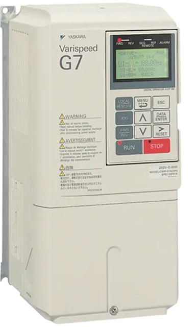
The Yaskawa General Purpose Inverter CIMR-G7C2045 is a versatile and efficient drive solution designed for a wide range of industrial applications. Known for its reliability and advanced features, this inverter optimizes motor control and enhances energy efficiency, making it an ideal choice for modern manufacturing environments.
Turn manuals into instant answers
with your AI-powered assistantTurn manuals into instant answers
with your AI-powered assistant
Manual for Yaskawa General Purpose Inverter CIMR-G7C2045
Complete asset maintenance, one click away
Get instant access to all the maintenance information you need. Empower technicians to perform preventive maintenance with asset packages, ready to use right out of the box.

Documents & Manuals
Find all the essential guides in one place.
 Tensioning Guide
- Belt-diagram
- C-120 pulleys
+ 13 more

Work Order Templates
Pre-built workflows to keep your asset running smoothly.
- Daily Electrical System Inspection
- Replace Roller and Pulley
- Install Engine B-120
+ 29 more

Procedures
Integrate maintenance plans directly into your work orders.
- Motion Industries
- Applied Industrial Technologies
- Electrical Brothers
+ 5 more

Parts
Access the parts list for your equipment in MaintainX.
- Drive Motor
- B2 Rollers
- Tensioning System
+ 40 more
Yaskawa General Purpose Inverter CIMR-G7C2045
Create an account to install this asset package.
Maintenance Plans for Yaskawa General Purpose Inverter Model CIMR-G7C2045
Integrate maintenance plans directly into your work orders in MaintainX.
10 Yearly Fuses Replacement
■ Maintenance and Inspection
⚠️ WARNING
• Do not touch the Inverter terminals. Some of the terminals carry high voltages and are extremely dangerous.; Doing so can result in electric shock.
• Always have the protective cover in place when power is being supplied to the Inverter. When attaching the cover, always turn OFF power to the Inverter through the MCCB.; Doing so can result in electric shock.
• After turning OFF the main circuit power supply, wait until the CHARGE indicator light goes out before performance maintenance or inspections.; The capacitor will remain charged and is dangerous.
• Maintenance, inspection, and replacement of parts must be performed only by authorized personnel.; Remove all metal objects, such as watches and rings, before starting work. Always use grounded tools. Failure to heed these warning can result in electric shock.
⚠️ CAUTION
• A CMOS IC is used in the control board. Handle the control board and CMOS IC carefully. The CMOS IC can be destroyed by static electricity if touched directly.; The CMOS IC can be destroyed by static electricity if touched directly.
• Do not change the wiring, or remove connectors or the Digital Operator, during operation.; Doing so can result in personal injury.

2 Yearly Cooling Fan Replacement
■ Maintenance and Inspection
⚠️ WARNING
• Do not touch the Inverter terminals. Some of the terminals carry high voltages and are extremely dangerous.; Doing so can result in electric shock.
• Always have the protective cover in place when power is being supplied to the Inverter. When attaching the cover, always turn OFF power to the Inverter through the MCCB.; Doing so can result in electric shock.
• After turning OFF the main circuit power supply, wait until the CHARGE indicator light goes out before performance maintenance or inspections.; The capacitor will remain charged and is dangerous.
• Maintenance, inspection, and replacement of parts must be performed only by authorized personnel.; Remove all metal objects, such as watches and rings, before starting work. Always use grounded tools. Failure to heed these warning can result in electric shock.
⚠️ CAUTION
• A CMOS IC is used in the control board. Handle the control board and CMOS IC carefully. The CMOS IC can be destroyed by static electricity if touched directly.; The CMOS IC can be destroyed by static electricity if touched directly.
• Do not change the wiring, or remove connectors or the Digital Operator, during operation.; Doing so can result in personal injury.
1 Daily General Purpose Inverter Inspection
WARNING: Do not touch the Inverter terminals. Some of the terminals carry high voltages and are extremely dangerous. Doing so can result in electric shock.
WARNING: Always have the protective cover in place when power is being supplied to the Inverter. When attaching the cover, always turn OFF power to the Inverter through the MCCB. Doing so can result in electric shock.
WARNING: After turning OFF the main circuit power supply, wait until the CHARGE indicator light goes out before performance maintenance or inspections. The capacitor will remain charged and is dangerous.
WARNING: Maintenance, inspection, and replacement of parts must be performed only by authorized personnel. Remove all metal objects, such as watches and rings, before starting work. Always use grounded tools. Failure to heed these warning can result in electric shock.
CAUTION: A CMOS IC is used in the control board. Handle the control board and CMOS IC carefully. The CMOS IC can be destroyed by static electricity if touched directly.
CAUTION: Do not change the wiring, or remove connectors or the Digital Operator, during operation. Doing so can result in personal injury.
The motor should not be vibrating or making unusual noises.
There should be no abnormal heat generation.
The ambient temperature should not be too high.
Breakers Relays Replacement
■ Maintenance and Inspection
⚠️ WARNING
• Do not touch the Inverter terminals. Some of the terminals carry high voltages and are extremely dangerous.; Doing so can result in electric shock.
• Always have the protective cover in place when power is being supplied to the Inverter. When attaching the cover, always turn OFF power to the Inverter through the MCCB.; Doing so can result in electric shock.
• After turning OFF the main circuit power supply, wait until the CHARGE indicator light goes out before performance maintenance or inspections.; The capacitor will remain charged and is dangerous.
• Maintenance, inspection, and replacement of parts must be performed only by authorized personnel.; Remove all metal objects, such as watches and rings, before starting work. Always use grounded tools. Failure to heed these warning can result in electric shock.
⚠️ CAUTION
• A CMOS IC is used in the control board. Handle the control board and CMOS IC carefully. The CMOS IC can be destroyed by static electricity if touched directly.; The CMOS IC can be destroyed by static electricity if touched directly.
• Do not change the wiring, or remove connectors or the Digital Operator, during operation.; Doing so can result in personal injury.
5 Yearly Capacitors Replacement
■ Maintenance and Inspection
⚠️ WARNING
• Do not touch the Inverter terminals. Some of the terminals carry high voltages and are extremely dangerous.; Doing so can result in electric shock.
• Always have the protective cover in place when power is being supplied to the Inverter. When attaching the cover, always turn OFF power to the Inverter through the MCCB.; Doing so can result in electric shock.
• After turning OFF the main circuit power supply, wait until the CHARGE indicator light goes out before performance maintenance or inspections.; The capacitor will remain charged and is dangerous.
• Maintenance, inspection, and replacement of parts must be performed only by authorized personnel.; Remove all metal objects, such as watches and rings, before starting work. Always use grounded tools. Failure to heed these warning can result in electric shock.
⚠️ CAUTION
• A CMOS IC is used in the control board. Handle the control board and CMOS IC carefully. The CMOS IC can be destroyed by static electricity if touched directly.; The CMOS IC can be destroyed by static electricity if touched directly.
• Do not change the wiring, or remove connectors or the Digital Operator, during operation.; Doing so can result in personal injury.
Parts for Yaskawa General Purpose Inverter CIMR-G7C2045
Access the parts list for your equipment in MaintainX.
Input Fuse 250 V 300 A
CR2L-300/UL
Noise Filter 300A, 11kg, 130 x 610 x 240
FS 5972-300-37
Input Fuse 250 V 300 A
CR2L-300/UL
Noise Filter 300A, 11kg, 130 x 610 x 240
FS 5972-300-37
Input Fuse 250 V 300 A
CR2L-300/UL
Noise Filter 300A, 11kg, 130 x 610 x 240
FS 5972-300-37
Unlock efficiency
with MaintainX CoPilot
MaintainX CoPilot is your expert colleague, on call 24/7, helping your team find the answers they need to keep equipment running.
Reduce Unplanned Downtime
Ensure your team follows consistent procedures to minimize equipment failures and costly delays.
Maximize Asset Availability
Keep your assets running longer and more reliably, with standardized maintenance workflows from OEM manuals.
Lower Maintenance Costs
Turn any technician into an expert to streamline operations, maintain more assets, and reduce overall costs.
Thousands of companies manage their assets with MaintainX

'%3e%3cpath%20fill='url(%23b)'%20d='M66.008%2080.068c-5.084-.786-9.763-3.834-12.442-8.68a16.942%2016.942%200%200%201-1.87-5.18c1.096.19%202.203.476%203.298.87%206.525%202.333%2010.836%207.68%2011.014%2012.99ZM51.47%2061.576c.488-5.524%203.62-10.716%208.847-13.597a17.132%2017.132%200%200%201%2011.335-1.882c-.798%208.145-7.43%2014.848-16.038%2015.599-1.417.119-2.799.07-4.144-.12Zm28.564-11.478a17.513%2017.513%200%200%201%203.727%204.62c4.608%208.335%201.584%2018.813-6.75%2023.409a16.988%2016.988%200%200%201-4.359%201.679%2019.624%2019.624%200%200%201-3.977-12.776c.346-7.561%204.942-13.931%2011.36-16.932Z'/%3e%3cpath%20fill='%23110F0D'%20fill-rule='evenodd'%20d='M142.831%2048.324h4.977V77.03h-4.977V48.324Zm27.278%2013.002c.322%201.048.453%202.263.453%203.62v12.073h-4.787V66.208c0-.75-.047-1.572-.154-2.143-.453-2.382-1.822-3.572-4.215-3.572-2.31%200-3.882%201.274-4.43%203.476-.143.596-.226%201.405-.226%202.25v10.8h-4.787V56.623h4.477v2.989c1.536-2.5%203.906-3.43%206.371-3.43%203.488%200%206.263%201.68%207.298%205.144Zm24.636%207.323c0%203.882-2.358%206.525-5.763%207.727-1.298.453-2.632.643-4.62.643h-10.169V48.324h9.085c1.691%200%203.156.143%204.049.38%203.465.93%205.727%203.68%205.727%207.335%200%202.441-.81%204.156-2.762%205.644%202.905%201.417%204.453%203.727%204.453%206.966Zm-15.634-8.656h4.584c1.024%200%201.917-.143%202.536-.417%201.215-.548%201.905-1.608%201.905-3.167%200-1.548-.643-2.572-1.845-3.132-.691-.31-1.762-.452-2.763-.452h-4.417v7.168Zm10.716%208.465c0-1.536-.893-3.37-3.227-3.893-.428-.095-1.036-.143-1.571-.143h-5.918v8.085h5.501c.56%200%201.429-.048%201.953-.167%201.94-.453%203.262-1.846%203.262-3.882Zm47.747-11.847-8.097%2020.408h-4.429l-8.109-20.408h5.191l5.192%2014.574%205.108-14.574h5.144Zm-20.218%2010.002c0%20.69-.036%201.262-.155%201.94h-15.943c.631%202.87%202.714%204.728%205.882%204.728%202.131%200%203.607-.882%204.703-2.525h4.87c-1.762%204.144-5.204%206.692-9.657%206.692-6.084%200-10.537-4.858-10.537-10.49%200-6.108%204.524-10.776%2010.335-10.776%206.239%200%2010.442%204.954%2010.502%2010.43Zm-4.763-1.405c-.333-2.846-2.643-4.858-5.691-4.858-2.894%200-5.287%201.929-5.621%204.858h11.312Zm-72.667%203.44c0%204.787-3.287%208.371-9.419%208.371H119.363V64.66c-1.917.274-3.87.69-5.811%201.238l4.537%2011.121h-5.418l-3.596-9.585c-5.144%202.084-10.085%205.216-14.217%209.585h-4.786L101.8%2048.312h4.56l5.68%2013.883a44.112%2044.112%200%200%201%207.323-1.774V48.312h9.084c1.703%200%203.156.143%204.061.393%203.453.929%205.727%203.667%205.727%207.323%200%201.917-.738%204.179-2.81%205.691%203.06%201.56%204.501%204.025%204.501%206.93Zm-15.634-8.667a62.664%2062.664%200%200%201%202.06-.036c1.703.012%203.239.131%204.608.37%201.441-.549%202.357-1.727%202.357-3.537%200-1.941-.881-3.144-2.488-3.667-.548-.18-1.358-.286-2.322-.286h-4.215v7.156Zm-16.55%203.905-3.715-9.894-6.394%2016.502c2.833-2.595%206.263-4.858%2010.109-6.608Zm27.254%204.74c0-2.775-3.131-4.347-8.513-4.418-.715%200-1.441.011-2.191.047v8.252h5.918c2.548%200%204.786-1.37%204.786-3.882Z'%20clip-rule='evenodd'/%3e%3c/g%3e%3cdefs%3e%3clinearGradient%20id='b'%20x1='51.47'%20x2='85.916'%20y1='62.946'%20y2='62.946'%20gradientUnits='userSpaceOnUse'%3e%3cstop%20stop-color='%23CD9F28'/%3e%3cstop%20offset='1'%20stop-color='%23ECD80B'/%3e%3c/linearGradient%3e%3cclipPath%20id='a'%3e%3cpath%20fill='%23fff'%20d='M51.47%2045.728h186.104V80.14H51.47z'/%3e%3c/clipPath%3e%3c/defs%3e%3c/svg%3e)


More from Yaskawa


Explore Other Assets


© 2026 MaintainX. All rights reserved.