


Trane Series R™ Helical Rotary Chiller RTHCE3F2F3
Need answers fast?
Explore the manual using AI.
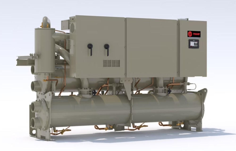
The Trane Series R™ Helical Rotary Chiller RTHCE3F2F3 is a high-efficiency industrial chiller designed for reliable cooling in large facilities. Known for its robust performance and energy efficiency, this model is ideal for various applications requiring precise temperature control and minimal downtime.
Turn manuals into instant answers
with your AI-powered assistantTurn manuals into instant answers
with your AI-powered assistant
Manual for Trane Series R™ Helical Rotary Chiller RTHCE3F2F3
Complete asset maintenance, one click away
Get instant access to all the maintenance information you need. Empower technicians to perform preventive maintenance with asset packages, ready to use right out of the box.

Documents & Manuals
Find all the essential guides in one place.
 Tensioning Guide
- Belt-diagram
- C-120 pulleys
+ 13 more

Work Order Templates
Pre-built workflows to keep your asset running smoothly.
- Daily Electrical System Inspection
- Replace Roller and Pulley
- Install Engine B-120
+ 29 more

Procedures
Integrate maintenance plans directly into your work orders.
- Motion Industries
- Applied Industrial Technologies
- Electrical Brothers
+ 5 more

Parts
Access the parts list for your equipment in MaintainX.
- Drive Motor
- B2 Rollers
- Tensioning System
+ 40 more
Trane Series R™ Helical Rotary Chiller RTHCE3F2F3
Create an account to install this asset package.
Maintenance Plans for Trane Series R™ Helical Rotary Chiller Model RTHCE3F2F3
Integrate maintenance plans directly into your work orders in MaintainX.
Compressor Oil Maintenance
CAUTION: To prevent oil sump heater burnout, open the unit main power disconnect switch before removing oil from the compressor.
Trane polyolester oil is the approved oil for the RTHC units. Polyolester oil is extremely hygroscopic meaning it readily attracts moisture. The oil can not be stored in plastic containers due to the hygroscopic properties. As with mineral oil, if water is in the system it will react with the oil to form acids.
Use Table 28 to determine the acceptability of the oil
Enter the proper charge amounts as given in Table 29
Did you use an oil transfer pump to change the oil regardless of chiller pressure?
Sign off on the compressor oil maintenance

The Condenser Cleaning
CAUTION: Do not use untreated or improperly treated water, or equipment damage may occur.
Is the 'approach' temperature higher than predicted?
If the approach exceeds 10°F cleaning the condenser tubes is recommended.
NOTE: Glycol in the water system typically doubles the standard approach.
Does the annual condenser tube inspection indicate that the tubes are fouled?
Choose the cleaning method
Mechanical Cleaning Procedure
Were the retaining bolts from the water boxes at each end of the condenser removed?
Was a round nylon- or brass- bristled brush worked in and out of each of the condenser water tubes to loosen the sludge?
1 Monthly Series R™ Helical Rotary Chiller Maintenance
Review operating log
Clean all water strainers in both the chilled and condensing water piping systems
Measure the oil filter pressure drop
Replace oil filter if required. Refer to “Service Procedures”
Measure and log the subcooling and superheat. Refer to Table 26
If operating conditions indicate a refrigerant shortage, leak check the unit using soap bubbles
Repair all leaks
Trim refrigerant charge until the unit operates in the conditions listed in Table 26 at full load, ARI conditions
NOTE: ARI conditions are: condenser water: 85°F and 3 GPM/XXX tons and evaporator water: 54-44°F
1 Yearly Series R™ Helical Rotary Chiller Maintenance
WARNING: Hazardous Voltage! Disconnect all electrical power, including remote disconnects before servicing. Failure to disconnect power before servicing can cause severe personal injury or death.
Perform all weekly and monthly maintenance procedures.
Check the refrigerant charge and oil level.
Routine oil changing is not necessary on a hermetic system.
Have a qualified laboratory perform an oil analysis to determine system moisture content and acid level.
IMPORTANT: Due to the hygroscopic properties of the POE oil, all oil must be stored in metal containers. The oil will absorb water if stored in a plastic container.
Check the pressure drop across the oil filter.
Contact a qualified service organization to leak check the chiller, to inspect safety controls, and inspect electrical components for deficiencies.
Inspect all piping components for leakage and damage. Clean out any inline strainers.
1 Weekly Series R™ Helical Rotary Chiller Maintenance
After the unit has operated for approximately 30 minutes and the system has stabilized, check the operating conditions and complete the procedures below:
Log the chiller.
Check evaporator and condenser pressures with gauges and compare to the reading on the Clear Language Display.
Pressure readings should fall within the following ranges specified in the Operating Conditions table:
NOTE: Optimum condenser pressure is dependent on condenser water temperature, and should equal the saturation pressure of the refrigerant at a temperature 2 to 5°F above that of leaving condenser water at full load.
Sign off on the weekly maintenance of the Series R™ Helical Rotary Chiller.
Parts for Trane Series R™ Helical Rotary Chiller RTHCE3F2F3
Access the parts list for your equipment in MaintainX.
Chiller
6200-0079-xx
Options
6200-0040-xx
Stepper
6200-0081-xx
LCLD (local CLD)
6200-0091-xx
TCI
6200-0093-xx
Chiller
6200-0079-xx
Options
6200-0040-xx
Stepper
6200-0081-xx
LCLD (local CLD)
6200-0091-xx
TCI
6200-0093-xx
Chiller
6200-0079-xx
Options
6200-0040-xx
Stepper
6200-0081-xx
LCLD (local CLD)
6200-0091-xx
TCI
6200-0093-xx
Unlock efficiency
with MaintainX CoPilot
MaintainX CoPilot is your expert colleague, on call 24/7, helping your team find the answers they need to keep equipment running.
Reduce Unplanned Downtime
Ensure your team follows consistent procedures to minimize equipment failures and costly delays.
Maximize Asset Availability
Keep your assets running longer and more reliably, with standardized maintenance workflows from OEM manuals.
Lower Maintenance Costs
Turn any technician into an expert to streamline operations, maintain more assets, and reduce overall costs.
Thousands of companies manage their assets with MaintainX

'%3e%3cpath%20fill='url(%23b)'%20d='M66.008%2080.068c-5.084-.786-9.763-3.834-12.442-8.68a16.942%2016.942%200%200%201-1.87-5.18c1.096.19%202.203.476%203.298.87%206.525%202.333%2010.836%207.68%2011.014%2012.99ZM51.47%2061.576c.488-5.524%203.62-10.716%208.847-13.597a17.132%2017.132%200%200%201%2011.335-1.882c-.798%208.145-7.43%2014.848-16.038%2015.599-1.417.119-2.799.07-4.144-.12Zm28.564-11.478a17.513%2017.513%200%200%201%203.727%204.62c4.608%208.335%201.584%2018.813-6.75%2023.409a16.988%2016.988%200%200%201-4.359%201.679%2019.624%2019.624%200%200%201-3.977-12.776c.346-7.561%204.942-13.931%2011.36-16.932Z'/%3e%3cpath%20fill='%23110F0D'%20fill-rule='evenodd'%20d='M142.831%2048.324h4.977V77.03h-4.977V48.324Zm27.278%2013.002c.322%201.048.453%202.263.453%203.62v12.073h-4.787V66.208c0-.75-.047-1.572-.154-2.143-.453-2.382-1.822-3.572-4.215-3.572-2.31%200-3.882%201.274-4.43%203.476-.143.596-.226%201.405-.226%202.25v10.8h-4.787V56.623h4.477v2.989c1.536-2.5%203.906-3.43%206.371-3.43%203.488%200%206.263%201.68%207.298%205.144Zm24.636%207.323c0%203.882-2.358%206.525-5.763%207.727-1.298.453-2.632.643-4.62.643h-10.169V48.324h9.085c1.691%200%203.156.143%204.049.38%203.465.93%205.727%203.68%205.727%207.335%200%202.441-.81%204.156-2.762%205.644%202.905%201.417%204.453%203.727%204.453%206.966Zm-15.634-8.656h4.584c1.024%200%201.917-.143%202.536-.417%201.215-.548%201.905-1.608%201.905-3.167%200-1.548-.643-2.572-1.845-3.132-.691-.31-1.762-.452-2.763-.452h-4.417v7.168Zm10.716%208.465c0-1.536-.893-3.37-3.227-3.893-.428-.095-1.036-.143-1.571-.143h-5.918v8.085h5.501c.56%200%201.429-.048%201.953-.167%201.94-.453%203.262-1.846%203.262-3.882Zm47.747-11.847-8.097%2020.408h-4.429l-8.109-20.408h5.191l5.192%2014.574%205.108-14.574h5.144Zm-20.218%2010.002c0%20.69-.036%201.262-.155%201.94h-15.943c.631%202.87%202.714%204.728%205.882%204.728%202.131%200%203.607-.882%204.703-2.525h4.87c-1.762%204.144-5.204%206.692-9.657%206.692-6.084%200-10.537-4.858-10.537-10.49%200-6.108%204.524-10.776%2010.335-10.776%206.239%200%2010.442%204.954%2010.502%2010.43Zm-4.763-1.405c-.333-2.846-2.643-4.858-5.691-4.858-2.894%200-5.287%201.929-5.621%204.858h11.312Zm-72.667%203.44c0%204.787-3.287%208.371-9.419%208.371H119.363V64.66c-1.917.274-3.87.69-5.811%201.238l4.537%2011.121h-5.418l-3.596-9.585c-5.144%202.084-10.085%205.216-14.217%209.585h-4.786L101.8%2048.312h4.56l5.68%2013.883a44.112%2044.112%200%200%201%207.323-1.774V48.312h9.084c1.703%200%203.156.143%204.061.393%203.453.929%205.727%203.667%205.727%207.323%200%201.917-.738%204.179-2.81%205.691%203.06%201.56%204.501%204.025%204.501%206.93Zm-15.634-8.667a62.664%2062.664%200%200%201%202.06-.036c1.703.012%203.239.131%204.608.37%201.441-.549%202.357-1.727%202.357-3.537%200-1.941-.881-3.144-2.488-3.667-.548-.18-1.358-.286-2.322-.286h-4.215v7.156Zm-16.55%203.905-3.715-9.894-6.394%2016.502c2.833-2.595%206.263-4.858%2010.109-6.608Zm27.254%204.74c0-2.775-3.131-4.347-8.513-4.418-.715%200-1.441.011-2.191.047v8.252h5.918c2.548%200%204.786-1.37%204.786-3.882Z'%20clip-rule='evenodd'/%3e%3c/g%3e%3cdefs%3e%3clinearGradient%20id='b'%20x1='51.47'%20x2='85.916'%20y1='62.946'%20y2='62.946'%20gradientUnits='userSpaceOnUse'%3e%3cstop%20stop-color='%23CD9F28'/%3e%3cstop%20offset='1'%20stop-color='%23ECD80B'/%3e%3c/linearGradient%3e%3cclipPath%20id='a'%3e%3cpath%20fill='%23fff'%20d='M51.47%2045.728h186.104V80.14H51.47z'/%3e%3c/clipPath%3e%3c/defs%3e%3c/svg%3e)


More from Trane


Explore Other Assets


© 2026 MaintainX. All rights reserved.