


Trane Series R™ Helical Rotary Chiller RTHCD2D2E2
Need answers fast?
Explore the manual using AI.
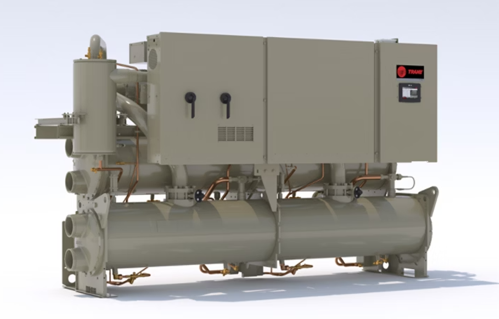
The Trane Series R™ Helical Rotary Chiller RTHCD2D2E2 is a high-efficiency industrial cooling solution designed for large-scale applications. Known for its reliability and advanced technology, this chiller optimizes energy consumption while providing superior cooling performance. Ideal for commercial and industrial environments, it ensures consistent temperature control and operational efficiency.
Turn manuals into instant answers
with your AI-powered assistantTurn manuals into instant answers
with your AI-powered assistant
Manual for Trane Series R™ Helical Rotary Chiller RTHCD2D2E2
Complete asset maintenance, one click away
Get instant access to all the maintenance information you need. Empower technicians to perform preventive maintenance with asset packages, ready to use right out of the box.

Documents & Manuals
Find all the essential guides in one place.
 Tensioning Guide
- Belt-diagram
- C-120 pulleys
+ 13 more

Work Order Templates
Pre-built workflows to keep your asset running smoothly.
- Daily Electrical System Inspection
- Replace Roller and Pulley
- Install Engine B-120
+ 29 more

Procedures
Integrate maintenance plans directly into your work orders.
- Motion Industries
- Applied Industrial Technologies
- Electrical Brothers
+ 5 more

Parts
Access the parts list for your equipment in MaintainX.
- Drive Motor
- B2 Rollers
- Tensioning System
+ 40 more
Trane Series R™ Helical Rotary Chiller RTHCD2D2E2
Create an account to install this asset package.
Maintenance Plans for Trane Series R™ Helical Rotary Chiller Model RTHCD2D2E2
Integrate maintenance plans directly into your work orders in MaintainX.
Refrigerant Charge
Warning: Disconnect ALL power before/during evacuation.
Cause of lost refrigerant determined and problem repaired?
Evacuation and Dehydration
Vacuum pump connected to the 5/8” flare connection on the bottom of the evaporator and/or condenser?
Enter the system pressure in microns after evacuation
Pressure below 500 microns?
Perform a standing rise test for at least an hour.
Enter the pressure rise in microns after the standing rise test
Pressure rise less than 150 microns?

Oil Sump Level Check
Warning: This procedure requires trained personnel with PPE!
Run the unit fully loaded for approximately 20 minutes.
Cycle the compressor off line.
Attach the 3/8” or 1/2” hose with a sightglass in the middle to the oil sump drain valve and the condenser service valve at the top of the condenser.
After the unit is off line for 10 minutes move the sightglass along the edge of the condenser tubesheet at the same height of the oil sump.
Enter the oil level from the bottom of the oil sump.
If the level appears to be above 8”, the oil sump is completely full. Most likely more oil resides in the rest of the system and some oil needs to be removed until the level falls between 2” and 5” in the oil sump.
If the level is below 2”, there is not enough oil in the sump. This can occur from not enough oil in the system or more likely, oil migration to the evaporator. Oil migration can occur from a low refrigerant charge, gas pump malfunction, etc.
Confirm the operation of the gas pump.
The Gas Pump Oil Filter Replacement
Warning: This procedure should be performed by trained personnel only.
Gas pump returning oil to the compressor?
Enter the liquid level reading from the sensor
Enter the suction pressure reading
Enter the evaporator approach reading
Is the pressure drop across the filter within the normal range at full load conditions?
If the oil is logged in the evaporator, manually move the oil from the evaporator to the oil sump.
Sign off on the oil filter replacement
The Condenser Cleaning
CAUTION: Do not use untreated or improperly treated water, or equipment damage may occur.
Condenser tube fouling is indicated when the “approach” temperature is higher than predicted.
Does the approach exceed 10°F?
If the approach exceeds 10°F cleaning the condenser tubes is recommended.
Choose the cleaning method
Mechanical Cleaning Procedure
Remove the retaining bolts from the water boxes at each end of the condenser.
Work a round nylon- or brass- bristled brush in and out of each of the condenser water tubes to loosen the sludge.
Thoroughly flush the condenser water tubes with clean water.
Oil Charging
Warning: This procedure requires trained personnel with PPE!
Locate the 1/4” schrader valve between the ball valve and oil filter (or the ball valve and oil cooler, if so equipped).
Loosely connect oil pump to schrader valve called out in step 1.
Operate oil charging pump until oil appears at the charging valve connection; then tighten the connection.
Note: To keep air from entering the oil, the charging valve connection must be air- tight.
Close the ball valve just upstream of the schrader valve connected to the oil pump.
At the UCP2 display panel, press <Service Tests> and enter the password (++--++) followed by <Enter>).
Press <enter> to access the service tools group.
Press <next> 12 times to display “Master Oil Line Solenoid Valve: [Mode]”.
Parts for Trane Series R™ Helical Rotary Chiller RTHCD2D2E2
Access the parts list for your equipment in MaintainX.
EXV
X15110743
Stepper
6200-0081-xx
Options
6200-0040-xx
CCCLD (Complex Character CLD)
6200-0092-xx
TCI
6200-0093-xx
EXV
X15110743
Stepper
6200-0081-xx
Options
6200-0040-xx
CCCLD (Complex Character CLD)
6200-0092-xx
TCI
6200-0093-xx
EXV
X15110743
Stepper
6200-0081-xx
Options
6200-0040-xx
CCCLD (Complex Character CLD)
6200-0092-xx
TCI
6200-0093-xx
Unlock efficiency
with MaintainX CoPilot
MaintainX CoPilot is your expert colleague, on call 24/7, helping your team find the answers they need to keep equipment running.
Reduce Unplanned Downtime
Ensure your team follows consistent procedures to minimize equipment failures and costly delays.
Maximize Asset Availability
Keep your assets running longer and more reliably, with standardized maintenance workflows from OEM manuals.
Lower Maintenance Costs
Turn any technician into an expert to streamline operations, maintain more assets, and reduce overall costs.
Thousands of companies manage their assets with MaintainX

'%3e%3cpath%20fill='url(%23b)'%20d='M66.008%2080.068c-5.084-.786-9.763-3.834-12.442-8.68a16.942%2016.942%200%200%201-1.87-5.18c1.096.19%202.203.476%203.298.87%206.525%202.333%2010.836%207.68%2011.014%2012.99ZM51.47%2061.576c.488-5.524%203.62-10.716%208.847-13.597a17.132%2017.132%200%200%201%2011.335-1.882c-.798%208.145-7.43%2014.848-16.038%2015.599-1.417.119-2.799.07-4.144-.12Zm28.564-11.478a17.513%2017.513%200%200%201%203.727%204.62c4.608%208.335%201.584%2018.813-6.75%2023.409a16.988%2016.988%200%200%201-4.359%201.679%2019.624%2019.624%200%200%201-3.977-12.776c.346-7.561%204.942-13.931%2011.36-16.932Z'/%3e%3cpath%20fill='%23110F0D'%20fill-rule='evenodd'%20d='M142.831%2048.324h4.977V77.03h-4.977V48.324Zm27.278%2013.002c.322%201.048.453%202.263.453%203.62v12.073h-4.787V66.208c0-.75-.047-1.572-.154-2.143-.453-2.382-1.822-3.572-4.215-3.572-2.31%200-3.882%201.274-4.43%203.476-.143.596-.226%201.405-.226%202.25v10.8h-4.787V56.623h4.477v2.989c1.536-2.5%203.906-3.43%206.371-3.43%203.488%200%206.263%201.68%207.298%205.144Zm24.636%207.323c0%203.882-2.358%206.525-5.763%207.727-1.298.453-2.632.643-4.62.643h-10.169V48.324h9.085c1.691%200%203.156.143%204.049.38%203.465.93%205.727%203.68%205.727%207.335%200%202.441-.81%204.156-2.762%205.644%202.905%201.417%204.453%203.727%204.453%206.966Zm-15.634-8.656h4.584c1.024%200%201.917-.143%202.536-.417%201.215-.548%201.905-1.608%201.905-3.167%200-1.548-.643-2.572-1.845-3.132-.691-.31-1.762-.452-2.763-.452h-4.417v7.168Zm10.716%208.465c0-1.536-.893-3.37-3.227-3.893-.428-.095-1.036-.143-1.571-.143h-5.918v8.085h5.501c.56%200%201.429-.048%201.953-.167%201.94-.453%203.262-1.846%203.262-3.882Zm47.747-11.847-8.097%2020.408h-4.429l-8.109-20.408h5.191l5.192%2014.574%205.108-14.574h5.144Zm-20.218%2010.002c0%20.69-.036%201.262-.155%201.94h-15.943c.631%202.87%202.714%204.728%205.882%204.728%202.131%200%203.607-.882%204.703-2.525h4.87c-1.762%204.144-5.204%206.692-9.657%206.692-6.084%200-10.537-4.858-10.537-10.49%200-6.108%204.524-10.776%2010.335-10.776%206.239%200%2010.442%204.954%2010.502%2010.43Zm-4.763-1.405c-.333-2.846-2.643-4.858-5.691-4.858-2.894%200-5.287%201.929-5.621%204.858h11.312Zm-72.667%203.44c0%204.787-3.287%208.371-9.419%208.371H119.363V64.66c-1.917.274-3.87.69-5.811%201.238l4.537%2011.121h-5.418l-3.596-9.585c-5.144%202.084-10.085%205.216-14.217%209.585h-4.786L101.8%2048.312h4.56l5.68%2013.883a44.112%2044.112%200%200%201%207.323-1.774V48.312h9.084c1.703%200%203.156.143%204.061.393%203.453.929%205.727%203.667%205.727%207.323%200%201.917-.738%204.179-2.81%205.691%203.06%201.56%204.501%204.025%204.501%206.93Zm-15.634-8.667a62.664%2062.664%200%200%201%202.06-.036c1.703.012%203.239.131%204.608.37%201.441-.549%202.357-1.727%202.357-3.537%200-1.941-.881-3.144-2.488-3.667-.548-.18-1.358-.286-2.322-.286h-4.215v7.156Zm-16.55%203.905-3.715-9.894-6.394%2016.502c2.833-2.595%206.263-4.858%2010.109-6.608Zm27.254%204.74c0-2.775-3.131-4.347-8.513-4.418-.715%200-1.441.011-2.191.047v8.252h5.918c2.548%200%204.786-1.37%204.786-3.882Z'%20clip-rule='evenodd'/%3e%3c/g%3e%3cdefs%3e%3clinearGradient%20id='b'%20x1='51.47'%20x2='85.916'%20y1='62.946'%20y2='62.946'%20gradientUnits='userSpaceOnUse'%3e%3cstop%20stop-color='%23CD9F28'/%3e%3cstop%20offset='1'%20stop-color='%23ECD80B'/%3e%3c/linearGradient%3e%3cclipPath%20id='a'%3e%3cpath%20fill='%23fff'%20d='M51.47%2045.728h186.104V80.14H51.47z'/%3e%3c/clipPath%3e%3c/defs%3e%3c/svg%3e)


More from Trane


Explore Other Assets


© 2026 MaintainX. All rights reserved.