


Trane Series R™ Helical Rotary Chiller RTAC250S
Need answers fast?
Explore the manual using AI.
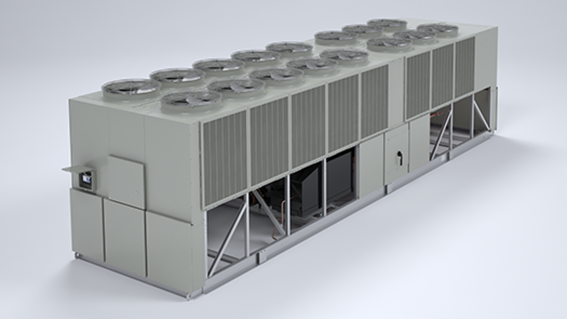
The Trane Series R™ Helical Rotary Chiller RTAC250S is a high-efficiency industrial chiller designed for optimal cooling performance. With advanced technology and robust construction, it ensures reliable operation and energy savings in commercial applications. Ideal for large facilities, this chiller provides superior temperature control and durability.
Turn manuals into instant answers
with your AI-powered assistantTurn manuals into instant answers
with your AI-powered assistant
Manual for Trane Series R™ Helical Rotary Chiller RTAC250S
Complete asset maintenance, one click away
Get instant access to all the maintenance information you need. Empower technicians to perform preventive maintenance with asset packages, ready to use right out of the box.

Documents & Manuals
Find all the essential guides in one place.
 Tensioning Guide
- Belt-diagram
- C-120 pulleys
+ 13 more

Work Order Templates
Pre-built workflows to keep your asset running smoothly.
- Daily Electrical System Inspection
- Replace Roller and Pulley
- Install Engine B-120
+ 29 more

Procedures
Integrate maintenance plans directly into your work orders.
- Motion Industries
- Applied Industrial Technologies
- Electrical Brothers
+ 5 more

Parts
Access the parts list for your equipment in MaintainX.
- Drive Motor
- B2 Rollers
- Tensioning System
+ 40 more
Trane Series R™ Helical Rotary Chiller RTAC250S
Create an account to install this asset package.
Maintenance Plans for Trane Series R™ Helical Rotary Chiller Model RTAC250S
Integrate maintenance plans directly into your work orders in MaintainX.
Factory (initial) Refrigerant Charging Procedure
Verify that the EXVs are OPEN
Attach vacuum hoses to evaporator service valves (one per circuit)
Open service valves
Attach charging hoses to the charging port on the liquid line filter (one per circuit)
Begin semi-automatic vacuum procedure
When vacuum is complete (indicated), manually isolate the unit from vacuum
Charge unit through the filter housing port per Table 1 - Table 4
When charging is complete, shut evaporator service valve
Disconnect vacuum and charging hoses

Inspection Checklist
Inspect the individual pieces of the shipment for obvious damage
Inspect the unit for concealed damage
If concealed damage is discovered, stop unpacking the shipment.
Upload photos of the damage
Provide evidence that the damage did not occur after delivery
Notify the carrier’s terminal of the damage immediately, by phone and by mail.
Enter the details of the carrier notified
Notify the Trane sales representative and arrange for repair.
Enter the details of the Trane sales representative notified
Evaporator Flow Switch
Specific connection and schematic wiring diagrams are shipped with the unit. Some piping and control schemes, particularly those using a single water pump for both chilled and hot water, must be analyzed to determine how and or if a flow sensing device will provide desired operation.
Follow the manufacturer’s recommendations for selection and installation procedures. General guidelines for flow switch installation are outlined below.
1. Mount the switch upright, with a minimum of 5 pipe diameters of straight hori-zontal run on each side. Do not install close to elbows, orifices or valves.
NOTE: The arrow on the switch must point in the direction of flow.
2. To prevent switch fluttering, remove all air from the water system.
NOTE: The CH530 provides a 6-second time delay after a “loss-of-flow” diagnostic before shutting the unit down. Contact a qualified service representative if nuisance machine shutdowns persist.
3. Adjust the switch to open when water flow falls below the minimum flow rate. Evaporator data is given in the General Information section. Flow switch contacts are closed on proof of water flow.
4. Install a pipe strainer in the entering evaporator water line to protect components from waterborne debris.;
High Side Charge Isolation
Circuit is off
Liquid line service valve is shut
Oil return line service valve is shut
Circuit started with the service tool (access compressor service view in Techview)
Discharge check valve closed after unit trip
Discharge isolation valve is closed
Oil line shut off valve is closed
Refrigerant remainder recovered
NOTE: Remaining vapor can be recovered/stored in the high side of the system. Be certain to follow proper recovery procedures to avoid introduction of non-condensable gases.
Refrigerant Filter Replacement
Warning: This procedure requires trained personnel with PPE!
Temperature downstream of the filter is 8°F (4.4°C) lower than the upstream temperature?
Is the unit undercharged?
EXV is closed?
Liquid line isolation valve is closed?
Ball valve on oil cooler liquid line is closed?
Upload a photo of the attached hose to service port on liquid line filter flange.
Refrigerant from liquid line evacuated and stored?
Hose removed?
Parts for Trane Series R™ Helical Rotary Chiller RTAC250S
Access the parts list for your equipment in MaintainX.
Isolator
X10140305620
Isolator
X10140305620
Isolator
X10140305620
Unlock efficiency
with MaintainX CoPilot
MaintainX CoPilot is your expert colleague, on call 24/7, helping your team find the answers they need to keep equipment running.
Reduce Unplanned Downtime
Ensure your team follows consistent procedures to minimize equipment failures and costly delays.
Maximize Asset Availability
Keep your assets running longer and more reliably, with standardized maintenance workflows from OEM manuals.
Lower Maintenance Costs
Turn any technician into an expert to streamline operations, maintain more assets, and reduce overall costs.
Thousands of companies manage their assets with MaintainX

'%3e%3cpath%20fill='url(%23b)'%20d='M66.008%2080.068c-5.084-.786-9.763-3.834-12.442-8.68a16.942%2016.942%200%200%201-1.87-5.18c1.096.19%202.203.476%203.298.87%206.525%202.333%2010.836%207.68%2011.014%2012.99ZM51.47%2061.576c.488-5.524%203.62-10.716%208.847-13.597a17.132%2017.132%200%200%201%2011.335-1.882c-.798%208.145-7.43%2014.848-16.038%2015.599-1.417.119-2.799.07-4.144-.12Zm28.564-11.478a17.513%2017.513%200%200%201%203.727%204.62c4.608%208.335%201.584%2018.813-6.75%2023.409a16.988%2016.988%200%200%201-4.359%201.679%2019.624%2019.624%200%200%201-3.977-12.776c.346-7.561%204.942-13.931%2011.36-16.932Z'/%3e%3cpath%20fill='%23110F0D'%20fill-rule='evenodd'%20d='M142.831%2048.324h4.977V77.03h-4.977V48.324Zm27.278%2013.002c.322%201.048.453%202.263.453%203.62v12.073h-4.787V66.208c0-.75-.047-1.572-.154-2.143-.453-2.382-1.822-3.572-4.215-3.572-2.31%200-3.882%201.274-4.43%203.476-.143.596-.226%201.405-.226%202.25v10.8h-4.787V56.623h4.477v2.989c1.536-2.5%203.906-3.43%206.371-3.43%203.488%200%206.263%201.68%207.298%205.144Zm24.636%207.323c0%203.882-2.358%206.525-5.763%207.727-1.298.453-2.632.643-4.62.643h-10.169V48.324h9.085c1.691%200%203.156.143%204.049.38%203.465.93%205.727%203.68%205.727%207.335%200%202.441-.81%204.156-2.762%205.644%202.905%201.417%204.453%203.727%204.453%206.966Zm-15.634-8.656h4.584c1.024%200%201.917-.143%202.536-.417%201.215-.548%201.905-1.608%201.905-3.167%200-1.548-.643-2.572-1.845-3.132-.691-.31-1.762-.452-2.763-.452h-4.417v7.168Zm10.716%208.465c0-1.536-.893-3.37-3.227-3.893-.428-.095-1.036-.143-1.571-.143h-5.918v8.085h5.501c.56%200%201.429-.048%201.953-.167%201.94-.453%203.262-1.846%203.262-3.882Zm47.747-11.847-8.097%2020.408h-4.429l-8.109-20.408h5.191l5.192%2014.574%205.108-14.574h5.144Zm-20.218%2010.002c0%20.69-.036%201.262-.155%201.94h-15.943c.631%202.87%202.714%204.728%205.882%204.728%202.131%200%203.607-.882%204.703-2.525h4.87c-1.762%204.144-5.204%206.692-9.657%206.692-6.084%200-10.537-4.858-10.537-10.49%200-6.108%204.524-10.776%2010.335-10.776%206.239%200%2010.442%204.954%2010.502%2010.43Zm-4.763-1.405c-.333-2.846-2.643-4.858-5.691-4.858-2.894%200-5.287%201.929-5.621%204.858h11.312Zm-72.667%203.44c0%204.787-3.287%208.371-9.419%208.371H119.363V64.66c-1.917.274-3.87.69-5.811%201.238l4.537%2011.121h-5.418l-3.596-9.585c-5.144%202.084-10.085%205.216-14.217%209.585h-4.786L101.8%2048.312h4.56l5.68%2013.883a44.112%2044.112%200%200%201%207.323-1.774V48.312h9.084c1.703%200%203.156.143%204.061.393%203.453.929%205.727%203.667%205.727%207.323%200%201.917-.738%204.179-2.81%205.691%203.06%201.56%204.501%204.025%204.501%206.93Zm-15.634-8.667a62.664%2062.664%200%200%201%202.06-.036c1.703.012%203.239.131%204.608.37%201.441-.549%202.357-1.727%202.357-3.537%200-1.941-.881-3.144-2.488-3.667-.548-.18-1.358-.286-2.322-.286h-4.215v7.156Zm-16.55%203.905-3.715-9.894-6.394%2016.502c2.833-2.595%206.263-4.858%2010.109-6.608Zm27.254%204.74c0-2.775-3.131-4.347-8.513-4.418-.715%200-1.441.011-2.191.047v8.252h5.918c2.548%200%204.786-1.37%204.786-3.882Z'%20clip-rule='evenodd'/%3e%3c/g%3e%3cdefs%3e%3clinearGradient%20id='b'%20x1='51.47'%20x2='85.916'%20y1='62.946'%20y2='62.946'%20gradientUnits='userSpaceOnUse'%3e%3cstop%20stop-color='%23CD9F28'/%3e%3cstop%20offset='1'%20stop-color='%23ECD80B'/%3e%3c/linearGradient%3e%3cclipPath%20id='a'%3e%3cpath%20fill='%23fff'%20d='M51.47%2045.728h186.104V80.14H51.47z'/%3e%3c/clipPath%3e%3c/defs%3e%3c/svg%3e)


More from Trane


Explore Other Assets


© 2026 MaintainX. All rights reserved.