


Trane Series R™ Helical Rotary Chiller RTAC200H
Need answers fast?
Explore the manual using AI.
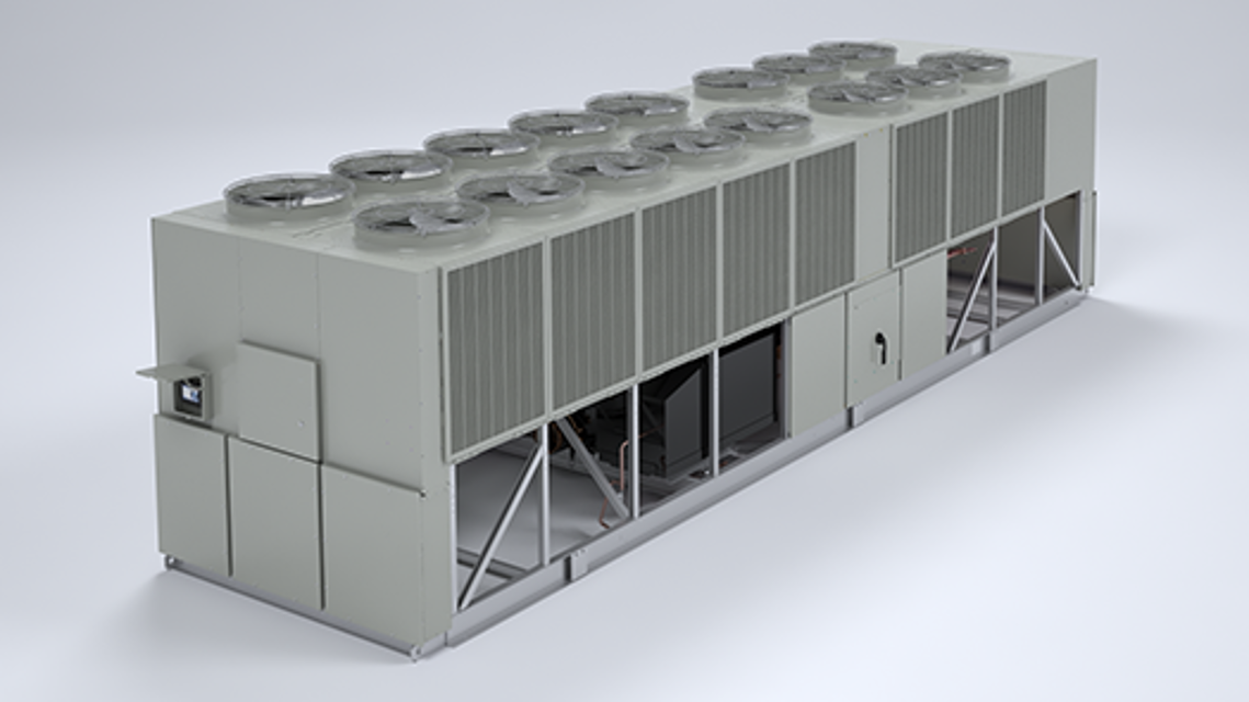
The Trane Series R™ Helical Rotary Chiller RTAC200H is a high-efficiency industrial chiller designed for optimal cooling performance. With advanced technology and robust construction, this model ensures reliable operation and energy savings for commercial applications. Ideal for large facilities, it provides consistent temperature control and is engineered for longevity.
Turn manuals into instant answers
with your AI-powered assistantTurn manuals into instant answers
with your AI-powered assistant
Manual for Trane Series R™ Helical Rotary Chiller RTAC200H
Complete asset maintenance, one click away
Get instant access to all the maintenance information you need. Empower technicians to perform preventive maintenance with asset packages, ready to use right out of the box.

Documents & Manuals
Find all the essential guides in one place.
 Tensioning Guide
- Belt-diagram
- C-120 pulleys
+ 13 more

Work Order Templates
Pre-built workflows to keep your asset running smoothly.
- Daily Electrical System Inspection
- Replace Roller and Pulley
- Install Engine B-120
+ 29 more

Procedures
Integrate maintenance plans directly into your work orders.
- Motion Industries
- Applied Industrial Technologies
- Electrical Brothers
+ 5 more

Parts
Access the parts list for your equipment in MaintainX.
- Drive Motor
- B2 Rollers
- Tensioning System
+ 40 more
Trane Series R™ Helical Rotary Chiller RTAC200H
Create an account to install this asset package.
Maintenance Plans for Trane Series R™ Helical Rotary Chiller Model RTAC200H
Integrate maintenance plans directly into your work orders in MaintainX.
Evaporator Flow Switch
Specific connection and schematic wiring diagrams are shipped with the unit. Some piping and control schemes, particularly those using a single water pump for both chilled and hot water, must be analyzed to determine how and or if a flow sensing device will provide desired operation.
Follow the manufacturer’s recommendations for selection and installation procedures. General guidelines for flow switch installation are outlined below.
1. Mount the switch upright, with a minimum of 5 pipe diameters of straight hori-zontal run on each side. Do not install close to elbows, orifices or valves.
NOTE: The arrow on the switch must point in the direction of flow.
2. To prevent switch fluttering, remove all air from the water system.
NOTE: The CH530 provides a 6-second time delay after a “loss-of-flow” diagnostic before shutting the unit down. Contact a qualified service representative if nuisance machine shutdowns persist.
3. Adjust the switch to open when water flow falls below the minimum flow rate. Evaporator data is given in the General Information section. Flow switch contacts are closed on proof of water flow.
4. Install a pipe strainer in the entering evaporator water line to protect components from waterborne debris.;

Field Refrigerant Charging
CAUTION: Evaporator Damage! Water must be flowing through the evaporator during the entire charging process to avoid freezing and rupturing of the evaporator tubes. Charge first with vapor to avoid freezing tubes.
Weight of the amount of charge removed
Does the weight of the charge removed match with the values in Table 1 - Table 4?
If there is a difference in charge, it may indicate a leak.
Is the charging hose attached to the evaporator service valve (3/8” (9mm) flare)?
Amount of charge added to the evaporator
Is the total circuit charge up to the level indicated in the chart?
Is the service valve closed and charging hose disconnected?
Sign off on the refrigerant charging process
Clearances
Ensure enough space around the outdoor unit for unrestricted access to all service points.
Enter the unit dimensions as per submittal drawings
Enter the minimum clearance for compressor service (Recommended: 4 feet or 1.2 m)
Enter the clearance for control panel doors
Local codes requiring additional clearances will take precedence over these recommendations.
Ensure unobstructed flow of condenser air for maintaining chiller capacity and operating efficiency.
Is there sufficient flow of air across the condenser heat transfer surface?
Avoid warm air recirculation and coil starvation.
Is there any warm air recirculation?
Neoprene Isolator Replacement
Secure the isolators to the mounting surface using the mounting slots in the isolator base plate. Do not fully tighten the isolator mounting bolts at this time.
Align the mounting holes in the base of the unit with the threaded positioning pins on the top of the isolators.
Lower the unit onto the isolators and secure the isolator to the unit with a nut. Maximum isolator deflection should be 1/4 inch (6 mm).
Level the unit carefully. Fully tighten the isolator mounting bolts.
Sign off on the isolator replacement
Returning Unit To Running Condition
All valves opened
EXV manually opened for 15 minutes
Water flowing in the evaporator prior to opening the EXV
Unit sat with heaters on to drive refrigerant out of oil and warm up compressor bearings
UCM powered so the pump may be energized if it detects a freeze condition
Oil level returned to normal
Unit put back into operation
Parts for Trane Series R™ Helical Rotary Chiller RTAC200H
Access the parts list for your equipment in MaintainX.
Isolator
X10140305620
Isolator
X10140305620
Isolator
X10140305620
Unlock efficiency
with MaintainX CoPilot
MaintainX CoPilot is your expert colleague, on call 24/7, helping your team find the answers they need to keep equipment running.
Reduce Unplanned Downtime
Ensure your team follows consistent procedures to minimize equipment failures and costly delays.
Maximize Asset Availability
Keep your assets running longer and more reliably, with standardized maintenance workflows from OEM manuals.
Lower Maintenance Costs
Turn any technician into an expert to streamline operations, maintain more assets, and reduce overall costs.
Thousands of companies manage their assets with MaintainX

'%3e%3cpath%20fill='url(%23b)'%20d='M66.008%2080.068c-5.084-.786-9.763-3.834-12.442-8.68a16.942%2016.942%200%200%201-1.87-5.18c1.096.19%202.203.476%203.298.87%206.525%202.333%2010.836%207.68%2011.014%2012.99ZM51.47%2061.576c.488-5.524%203.62-10.716%208.847-13.597a17.132%2017.132%200%200%201%2011.335-1.882c-.798%208.145-7.43%2014.848-16.038%2015.599-1.417.119-2.799.07-4.144-.12Zm28.564-11.478a17.513%2017.513%200%200%201%203.727%204.62c4.608%208.335%201.584%2018.813-6.75%2023.409a16.988%2016.988%200%200%201-4.359%201.679%2019.624%2019.624%200%200%201-3.977-12.776c.346-7.561%204.942-13.931%2011.36-16.932Z'/%3e%3cpath%20fill='%23110F0D'%20fill-rule='evenodd'%20d='M142.831%2048.324h4.977V77.03h-4.977V48.324Zm27.278%2013.002c.322%201.048.453%202.263.453%203.62v12.073h-4.787V66.208c0-.75-.047-1.572-.154-2.143-.453-2.382-1.822-3.572-4.215-3.572-2.31%200-3.882%201.274-4.43%203.476-.143.596-.226%201.405-.226%202.25v10.8h-4.787V56.623h4.477v2.989c1.536-2.5%203.906-3.43%206.371-3.43%203.488%200%206.263%201.68%207.298%205.144Zm24.636%207.323c0%203.882-2.358%206.525-5.763%207.727-1.298.453-2.632.643-4.62.643h-10.169V48.324h9.085c1.691%200%203.156.143%204.049.38%203.465.93%205.727%203.68%205.727%207.335%200%202.441-.81%204.156-2.762%205.644%202.905%201.417%204.453%203.727%204.453%206.966Zm-15.634-8.656h4.584c1.024%200%201.917-.143%202.536-.417%201.215-.548%201.905-1.608%201.905-3.167%200-1.548-.643-2.572-1.845-3.132-.691-.31-1.762-.452-2.763-.452h-4.417v7.168Zm10.716%208.465c0-1.536-.893-3.37-3.227-3.893-.428-.095-1.036-.143-1.571-.143h-5.918v8.085h5.501c.56%200%201.429-.048%201.953-.167%201.94-.453%203.262-1.846%203.262-3.882Zm47.747-11.847-8.097%2020.408h-4.429l-8.109-20.408h5.191l5.192%2014.574%205.108-14.574h5.144Zm-20.218%2010.002c0%20.69-.036%201.262-.155%201.94h-15.943c.631%202.87%202.714%204.728%205.882%204.728%202.131%200%203.607-.882%204.703-2.525h4.87c-1.762%204.144-5.204%206.692-9.657%206.692-6.084%200-10.537-4.858-10.537-10.49%200-6.108%204.524-10.776%2010.335-10.776%206.239%200%2010.442%204.954%2010.502%2010.43Zm-4.763-1.405c-.333-2.846-2.643-4.858-5.691-4.858-2.894%200-5.287%201.929-5.621%204.858h11.312Zm-72.667%203.44c0%204.787-3.287%208.371-9.419%208.371H119.363V64.66c-1.917.274-3.87.69-5.811%201.238l4.537%2011.121h-5.418l-3.596-9.585c-5.144%202.084-10.085%205.216-14.217%209.585h-4.786L101.8%2048.312h4.56l5.68%2013.883a44.112%2044.112%200%200%201%207.323-1.774V48.312h9.084c1.703%200%203.156.143%204.061.393%203.453.929%205.727%203.667%205.727%207.323%200%201.917-.738%204.179-2.81%205.691%203.06%201.56%204.501%204.025%204.501%206.93Zm-15.634-8.667a62.664%2062.664%200%200%201%202.06-.036c1.703.012%203.239.131%204.608.37%201.441-.549%202.357-1.727%202.357-3.537%200-1.941-.881-3.144-2.488-3.667-.548-.18-1.358-.286-2.322-.286h-4.215v7.156Zm-16.55%203.905-3.715-9.894-6.394%2016.502c2.833-2.595%206.263-4.858%2010.109-6.608Zm27.254%204.74c0-2.775-3.131-4.347-8.513-4.418-.715%200-1.441.011-2.191.047v8.252h5.918c2.548%200%204.786-1.37%204.786-3.882Z'%20clip-rule='evenodd'/%3e%3c/g%3e%3cdefs%3e%3clinearGradient%20id='b'%20x1='51.47'%20x2='85.916'%20y1='62.946'%20y2='62.946'%20gradientUnits='userSpaceOnUse'%3e%3cstop%20stop-color='%23CD9F28'/%3e%3cstop%20offset='1'%20stop-color='%23ECD80B'/%3e%3c/linearGradient%3e%3cclipPath%20id='a'%3e%3cpath%20fill='%23fff'%20d='M51.47%2045.728h186.104V80.14H51.47z'/%3e%3c/clipPath%3e%3c/defs%3e%3c/svg%3e)


More from Trane


Explore Other Assets


© 2026 MaintainX. All rights reserved.