


Trane Series R™ Helical Rotary Chiller RTAC140S
Need answers fast?
Explore the manual using AI.
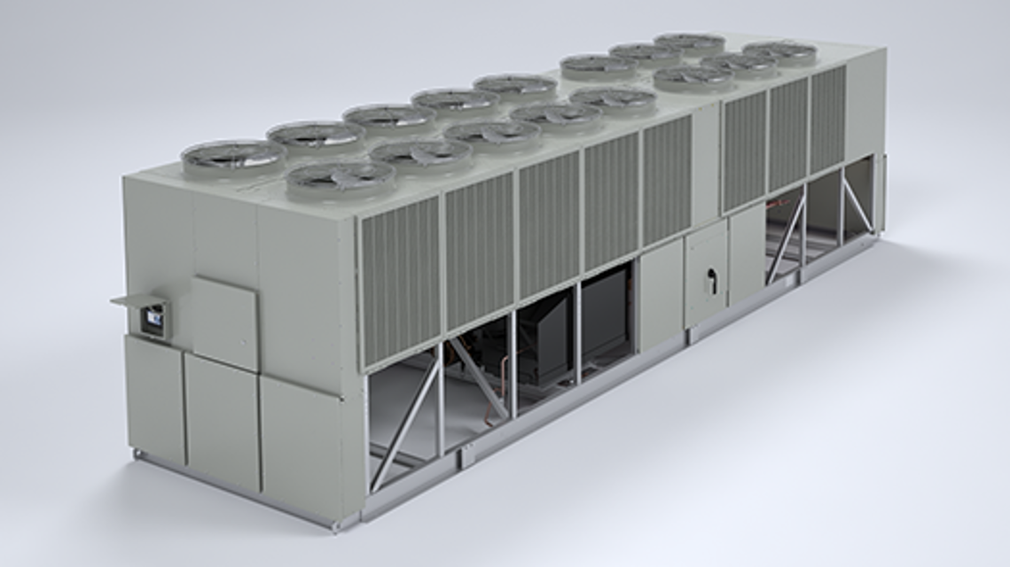
The Trane Series R™ Helical Rotary Chiller RTAC140S is a high-efficiency industrial chiller designed for optimal cooling performance. With advanced technology and robust construction, it ensures reliable operation and energy savings for large-scale applications. Ideal for commercial and industrial use, this model delivers superior reliability and efficiency.
Turn manuals into instant answers
with your AI-powered assistantTurn manuals into instant answers
with your AI-powered assistant
Manual for Trane Series R™ Helical Rotary Chiller RTAC140S
Complete asset maintenance, one click away
Get instant access to all the maintenance information you need. Empower technicians to perform preventive maintenance with asset packages, ready to use right out of the box.

Documents & Manuals
Find all the essential guides in one place.
 Tensioning Guide
- Belt-diagram
- C-120 pulleys
+ 13 more

Work Order Templates
Pre-built workflows to keep your asset running smoothly.
- Daily Electrical System Inspection
- Replace Roller and Pulley
- Install Engine B-120
+ 29 more

Procedures
Integrate maintenance plans directly into your work orders.
- Motion Industries
- Applied Industrial Technologies
- Electrical Brothers
+ 5 more

Parts
Access the parts list for your equipment in MaintainX.
- Drive Motor
- B2 Rollers
- Tensioning System
+ 40 more
Trane Series R™ Helical Rotary Chiller RTAC140S
Create an account to install this asset package.
Maintenance Plans for Trane Series R™ Helical Rotary Chiller Model RTAC140S
Integrate maintenance plans directly into your work orders in MaintainX.
Low Side Charge Isolation
Circuit is off
Suction line isolation valve is closed
Oil return line service valve is closed
Liquid line service valve is closed
EXV is manually opened
Select the method used to move refrigerant from the condenser to evaporator
NOTE: If a pump is to be used, connect it before closing this valve. This port is only isolated when the valve is back seated. If a vacuum pump is used, then connect it to the discharge line service valve near the oil separator.
Evaporator is large enough to hold all the charge for any unit to below the center-line of the shell
Sign off on the Low Side Charge Isolation

High Side Charge Isolation
Circuit is off
Liquid line service valve is shut
Oil return line service valve is shut
Circuit started with the service tool (access compressor service view in Techview)
Discharge check valve closed after unit trip
Discharge isolation valve is closed
Oil line shut off valve is closed
Refrigerant remainder recovered
NOTE: Remaining vapor can be recovered/stored in the high side of the system. Be certain to follow proper recovery procedures to avoid introduction of non-condensable gases.
Returning Unit To Running Condition
Open all valves
Manually open EXV for 15 minutes to allow refrigerant to drain to evaporator by gravity (ensure water is flowing in the evaporator prior to opening the EXV)
Let unit sit with heaters on to drive refrigerant out of oil and warm up compressor bearings. Depending upon ambient conditions, this may take up to 24 hours.Ensure the UCM is powered so the pump may be energized if it detects a freeze condition
Once the oil level has returned to normal, the unit can be put back into operation
Refrigerant and Oil Charge Management
Proper oil and refrigerant charge is essential for proper unit operation, unit perfor-mance, and environmental protection. Only trained and licensed service personnal should service the chiller.
Some symptoms of a refrigerant under-charged unit:
• Low subcooling
• Higher than normal discharge superheat
• Bubbles in EXV sight glass
• Low liquid level diagnostic
• Larger than normal evaporator approach temperatures (leaving water temperature - saturated evaporator temperature)
• Low evaporator refrigerant temperature limit
• Low refrigerant temperature cutout diagnostic
Clearances
Warning: This procedure requires trained personnel with PPE!
Is there enough space around the outdoor unit?
Enter the dimensions of the unit
Is there a minimum of 4 feet (1.2 m) for compressor service?
Is there sufficient clearance for the opening of control panel doors?
In all cases, local codes which require additional clearances will take precedence over these recommendations.
Is there unobstructed flow of condenser air?
Is there any warm air recirculation?
Is there any coil starvation?
Parts for Trane Series R™ Helical Rotary Chiller RTAC140S
Access the parts list for your equipment in MaintainX.
Isolator
X10140305620
Isolator
X10140305620
Isolator
X10140305620
Unlock efficiency
with MaintainX CoPilot
MaintainX CoPilot is your expert colleague, on call 24/7, helping your team find the answers they need to keep equipment running.
Reduce Unplanned Downtime
Ensure your team follows consistent procedures to minimize equipment failures and costly delays.
Maximize Asset Availability
Keep your assets running longer and more reliably, with standardized maintenance workflows from OEM manuals.
Lower Maintenance Costs
Turn any technician into an expert to streamline operations, maintain more assets, and reduce overall costs.
Thousands of companies manage their assets with MaintainX

'%3e%3cpath%20fill='url(%23b)'%20d='M66.008%2080.068c-5.084-.786-9.763-3.834-12.442-8.68a16.942%2016.942%200%200%201-1.87-5.18c1.096.19%202.203.476%203.298.87%206.525%202.333%2010.836%207.68%2011.014%2012.99ZM51.47%2061.576c.488-5.524%203.62-10.716%208.847-13.597a17.132%2017.132%200%200%201%2011.335-1.882c-.798%208.145-7.43%2014.848-16.038%2015.599-1.417.119-2.799.07-4.144-.12Zm28.564-11.478a17.513%2017.513%200%200%201%203.727%204.62c4.608%208.335%201.584%2018.813-6.75%2023.409a16.988%2016.988%200%200%201-4.359%201.679%2019.624%2019.624%200%200%201-3.977-12.776c.346-7.561%204.942-13.931%2011.36-16.932Z'/%3e%3cpath%20fill='%23110F0D'%20fill-rule='evenodd'%20d='M142.831%2048.324h4.977V77.03h-4.977V48.324Zm27.278%2013.002c.322%201.048.453%202.263.453%203.62v12.073h-4.787V66.208c0-.75-.047-1.572-.154-2.143-.453-2.382-1.822-3.572-4.215-3.572-2.31%200-3.882%201.274-4.43%203.476-.143.596-.226%201.405-.226%202.25v10.8h-4.787V56.623h4.477v2.989c1.536-2.5%203.906-3.43%206.371-3.43%203.488%200%206.263%201.68%207.298%205.144Zm24.636%207.323c0%203.882-2.358%206.525-5.763%207.727-1.298.453-2.632.643-4.62.643h-10.169V48.324h9.085c1.691%200%203.156.143%204.049.38%203.465.93%205.727%203.68%205.727%207.335%200%202.441-.81%204.156-2.762%205.644%202.905%201.417%204.453%203.727%204.453%206.966Zm-15.634-8.656h4.584c1.024%200%201.917-.143%202.536-.417%201.215-.548%201.905-1.608%201.905-3.167%200-1.548-.643-2.572-1.845-3.132-.691-.31-1.762-.452-2.763-.452h-4.417v7.168Zm10.716%208.465c0-1.536-.893-3.37-3.227-3.893-.428-.095-1.036-.143-1.571-.143h-5.918v8.085h5.501c.56%200%201.429-.048%201.953-.167%201.94-.453%203.262-1.846%203.262-3.882Zm47.747-11.847-8.097%2020.408h-4.429l-8.109-20.408h5.191l5.192%2014.574%205.108-14.574h5.144Zm-20.218%2010.002c0%20.69-.036%201.262-.155%201.94h-15.943c.631%202.87%202.714%204.728%205.882%204.728%202.131%200%203.607-.882%204.703-2.525h4.87c-1.762%204.144-5.204%206.692-9.657%206.692-6.084%200-10.537-4.858-10.537-10.49%200-6.108%204.524-10.776%2010.335-10.776%206.239%200%2010.442%204.954%2010.502%2010.43Zm-4.763-1.405c-.333-2.846-2.643-4.858-5.691-4.858-2.894%200-5.287%201.929-5.621%204.858h11.312Zm-72.667%203.44c0%204.787-3.287%208.371-9.419%208.371H119.363V64.66c-1.917.274-3.87.69-5.811%201.238l4.537%2011.121h-5.418l-3.596-9.585c-5.144%202.084-10.085%205.216-14.217%209.585h-4.786L101.8%2048.312h4.56l5.68%2013.883a44.112%2044.112%200%200%201%207.323-1.774V48.312h9.084c1.703%200%203.156.143%204.061.393%203.453.929%205.727%203.667%205.727%207.323%200%201.917-.738%204.179-2.81%205.691%203.06%201.56%204.501%204.025%204.501%206.93Zm-15.634-8.667a62.664%2062.664%200%200%201%202.06-.036c1.703.012%203.239.131%204.608.37%201.441-.549%202.357-1.727%202.357-3.537%200-1.941-.881-3.144-2.488-3.667-.548-.18-1.358-.286-2.322-.286h-4.215v7.156Zm-16.55%203.905-3.715-9.894-6.394%2016.502c2.833-2.595%206.263-4.858%2010.109-6.608Zm27.254%204.74c0-2.775-3.131-4.347-8.513-4.418-.715%200-1.441.011-2.191.047v8.252h5.918c2.548%200%204.786-1.37%204.786-3.882Z'%20clip-rule='evenodd'/%3e%3c/g%3e%3cdefs%3e%3clinearGradient%20id='b'%20x1='51.47'%20x2='85.916'%20y1='62.946'%20y2='62.946'%20gradientUnits='userSpaceOnUse'%3e%3cstop%20stop-color='%23CD9F28'/%3e%3cstop%20offset='1'%20stop-color='%23ECD80B'/%3e%3c/linearGradient%3e%3cclipPath%20id='a'%3e%3cpath%20fill='%23fff'%20d='M51.47%2045.728h186.104V80.14H51.47z'/%3e%3c/clipPath%3e%3c/defs%3e%3c/svg%3e)


More from Trane


Explore Other Assets


© 2026 MaintainX. All rights reserved.