


Trane Series R™ Helical Rotary Chiller RTAC120H
Need answers fast?
Explore the manual using AI.
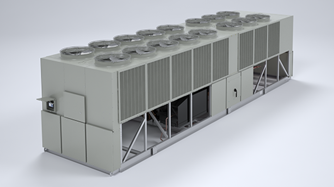
The Trane Series R™ Helical Rotary Chiller RTAC120H is a high-efficiency industrial chiller designed for reliable cooling in large facilities. With advanced technology and robust construction, it ensures optimal performance and energy savings, making it an ideal choice for commercial applications.
Turn manuals into instant answers
with your AI-powered assistantTurn manuals into instant answers
with your AI-powered assistant
Manual for Trane Series R™ Helical Rotary Chiller RTAC120H
Complete asset maintenance, one click away
Get instant access to all the maintenance information you need. Empower technicians to perform preventive maintenance with asset packages, ready to use right out of the box.

Documents & Manuals
Find all the essential guides in one place.
 Tensioning Guide
- Belt-diagram
- C-120 pulleys
+ 13 more

Work Order Templates
Pre-built workflows to keep your asset running smoothly.
- Daily Electrical System Inspection
- Replace Roller and Pulley
- Install Engine B-120
+ 29 more

Procedures
Integrate maintenance plans directly into your work orders.
- Motion Industries
- Applied Industrial Technologies
- Electrical Brothers
+ 5 more

Parts
Access the parts list for your equipment in MaintainX.
- Drive Motor
- B2 Rollers
- Tensioning System
+ 40 more
Trane Series R™ Helical Rotary Chiller RTAC120H
Create an account to install this asset package.
Maintenance Plans for Trane Series R™ Helical Rotary Chiller Model RTAC120H
Integrate maintenance plans directly into your work orders in MaintainX.
Adding Charge:
This procedure should be followed when adding charge to an undercharged unit. When low charge is indicated by low subcooling in the liquid line, charge should be added until sufficient subcooling is achieved.
1. Attach charging hose to evaporator service valve (3/8” (9mm) flare). Open service valve.
2. Add 10 pounds of refrigerant (R-134a) charge.
3. Close valve, remove charging hose and start unit. Monitor subcooling.
4. If subcooling is still insufficient, return to step #1.
NOTE: Proper subcooling can be determined from run log history, service experience, or by contacting Trane technical service.;

1 Yearly Series R™ Helical Rotary Chiller Maintenance
1. Perform all weekly and monthly procedures.
2. Check oil sump oil level while unit is off.
NOTE: Routine changing of the oil is not required. Use an oil analysis to determine the condition of the oil.
3. Have a qualified laboratory perform a compressor oil analysis to determine sys-tem moisture content and acid level. This analysis is a valuable diagnostic tool.
4. Contact a qualified service organization to leak test the chiller, to check operating and safety controls, and to inspect electrical components for deficiencies.
5. Inspect all piping components for leakage and damage. Clean out any inline strainers.
6. Clean and repaint any areas that show signs of corrosion.
7. Clean the condenser coils.
WARNING
Evaporator Flow Switch
Specific connection and schematic wiring diagrams are shipped with the unit. Some piping and control schemes, particularly those using a single water pump for both chilled and hot water, must be analyzed to determine how and or if a flow sensing device will provide desired operation.
Follow the manufacturer’s recommendations for selection and installation procedures. General guidelines for flow switch installation are outlined below.
1. Mount the switch upright, with a minimum of 5 pipe diameters of straight hori-zontal run on each side. Do not install close to elbows, orifices or valves.
NOTE: The arrow on the switch must point in the direction of flow.
2. To prevent switch fluttering, remove all air from the water system.
NOTE: The CH530 provides a 6-second time delay after a “loss-of-flow” diagnostic before shutting the unit down. Contact a qualified service representative if nuisance machine shutdowns persist.
3. Adjust the switch to open when water flow falls below the minimum flow rate. Evaporator data is given in the General Information section. Flow switch contacts are closed on proof of water flow.
4. Install a pipe strainer in the entering evaporator water line to protect components from waterborne debris.;
Refrigerant Filter Replacement
Warning: This procedure requires trained personnel with PPE!
Temperature downstream of the filter is 8°F (4.4°C) lower than the upstream temperature?
Unit is properly subcooled?
EXV is closed?
Liquid line isolation valve is closed?
Ball valve on oil cooler liquid line is closed?
Upload a photo of the attached hose to service port on liquid line filter flange.
Refrigerant from liquid line evacuated and stored?
Hose removed?
Inspection Checklist
Inspect the individual pieces of the shipment for obvious damage
Inspect the unit for concealed damage
Date of concealed damage report
Upload photos of the damage
Evidence that the damage did not occur after delivery
Carrier’s terminal notified of the damage
Trane sales representative notified and repair arranged
Do not repair the unit until damage is inspected by the carrier’s representative.
Sign off on the inspection checklist
Parts for Trane Series R™ Helical Rotary Chiller RTAC120H
Access the parts list for your equipment in MaintainX.
Isolator
X10140305620
Isolator
X10140305620
Isolator
X10140305620
Unlock efficiency
with MaintainX CoPilot
MaintainX CoPilot is your expert colleague, on call 24/7, helping your team find the answers they need to keep equipment running.
Reduce Unplanned Downtime
Ensure your team follows consistent procedures to minimize equipment failures and costly delays.
Maximize Asset Availability
Keep your assets running longer and more reliably, with standardized maintenance workflows from OEM manuals.
Lower Maintenance Costs
Turn any technician into an expert to streamline operations, maintain more assets, and reduce overall costs.
Thousands of companies manage their assets with MaintainX

'%3e%3cpath%20fill='url(%23b)'%20d='M66.008%2080.068c-5.084-.786-9.763-3.834-12.442-8.68a16.942%2016.942%200%200%201-1.87-5.18c1.096.19%202.203.476%203.298.87%206.525%202.333%2010.836%207.68%2011.014%2012.99ZM51.47%2061.576c.488-5.524%203.62-10.716%208.847-13.597a17.132%2017.132%200%200%201%2011.335-1.882c-.798%208.145-7.43%2014.848-16.038%2015.599-1.417.119-2.799.07-4.144-.12Zm28.564-11.478a17.513%2017.513%200%200%201%203.727%204.62c4.608%208.335%201.584%2018.813-6.75%2023.409a16.988%2016.988%200%200%201-4.359%201.679%2019.624%2019.624%200%200%201-3.977-12.776c.346-7.561%204.942-13.931%2011.36-16.932Z'/%3e%3cpath%20fill='%23110F0D'%20fill-rule='evenodd'%20d='M142.831%2048.324h4.977V77.03h-4.977V48.324Zm27.278%2013.002c.322%201.048.453%202.263.453%203.62v12.073h-4.787V66.208c0-.75-.047-1.572-.154-2.143-.453-2.382-1.822-3.572-4.215-3.572-2.31%200-3.882%201.274-4.43%203.476-.143.596-.226%201.405-.226%202.25v10.8h-4.787V56.623h4.477v2.989c1.536-2.5%203.906-3.43%206.371-3.43%203.488%200%206.263%201.68%207.298%205.144Zm24.636%207.323c0%203.882-2.358%206.525-5.763%207.727-1.298.453-2.632.643-4.62.643h-10.169V48.324h9.085c1.691%200%203.156.143%204.049.38%203.465.93%205.727%203.68%205.727%207.335%200%202.441-.81%204.156-2.762%205.644%202.905%201.417%204.453%203.727%204.453%206.966Zm-15.634-8.656h4.584c1.024%200%201.917-.143%202.536-.417%201.215-.548%201.905-1.608%201.905-3.167%200-1.548-.643-2.572-1.845-3.132-.691-.31-1.762-.452-2.763-.452h-4.417v7.168Zm10.716%208.465c0-1.536-.893-3.37-3.227-3.893-.428-.095-1.036-.143-1.571-.143h-5.918v8.085h5.501c.56%200%201.429-.048%201.953-.167%201.94-.453%203.262-1.846%203.262-3.882Zm47.747-11.847-8.097%2020.408h-4.429l-8.109-20.408h5.191l5.192%2014.574%205.108-14.574h5.144Zm-20.218%2010.002c0%20.69-.036%201.262-.155%201.94h-15.943c.631%202.87%202.714%204.728%205.882%204.728%202.131%200%203.607-.882%204.703-2.525h4.87c-1.762%204.144-5.204%206.692-9.657%206.692-6.084%200-10.537-4.858-10.537-10.49%200-6.108%204.524-10.776%2010.335-10.776%206.239%200%2010.442%204.954%2010.502%2010.43Zm-4.763-1.405c-.333-2.846-2.643-4.858-5.691-4.858-2.894%200-5.287%201.929-5.621%204.858h11.312Zm-72.667%203.44c0%204.787-3.287%208.371-9.419%208.371H119.363V64.66c-1.917.274-3.87.69-5.811%201.238l4.537%2011.121h-5.418l-3.596-9.585c-5.144%202.084-10.085%205.216-14.217%209.585h-4.786L101.8%2048.312h4.56l5.68%2013.883a44.112%2044.112%200%200%201%207.323-1.774V48.312h9.084c1.703%200%203.156.143%204.061.393%203.453.929%205.727%203.667%205.727%207.323%200%201.917-.738%204.179-2.81%205.691%203.06%201.56%204.501%204.025%204.501%206.93Zm-15.634-8.667a62.664%2062.664%200%200%201%202.06-.036c1.703.012%203.239.131%204.608.37%201.441-.549%202.357-1.727%202.357-3.537%200-1.941-.881-3.144-2.488-3.667-.548-.18-1.358-.286-2.322-.286h-4.215v7.156Zm-16.55%203.905-3.715-9.894-6.394%2016.502c2.833-2.595%206.263-4.858%2010.109-6.608Zm27.254%204.74c0-2.775-3.131-4.347-8.513-4.418-.715%200-1.441.011-2.191.047v8.252h5.918c2.548%200%204.786-1.37%204.786-3.882Z'%20clip-rule='evenodd'/%3e%3c/g%3e%3cdefs%3e%3clinearGradient%20id='b'%20x1='51.47'%20x2='85.916'%20y1='62.946'%20y2='62.946'%20gradientUnits='userSpaceOnUse'%3e%3cstop%20stop-color='%23CD9F28'/%3e%3cstop%20offset='1'%20stop-color='%23ECD80B'/%3e%3c/linearGradient%3e%3cclipPath%20id='a'%3e%3cpath%20fill='%23fff'%20d='M51.47%2045.728h186.104V80.14H51.47z'/%3e%3c/clipPath%3e%3c/defs%3e%3c/svg%3e)


More from Trane


Explore Other Assets


© 2026 MaintainX. All rights reserved.