


Gardner Denver Compressor VS45A
Need answers fast?
Explore the manual using AI.
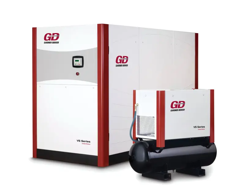
The Gardner Denver Compressor VS45A is a robust industrial air compressor designed for high efficiency and reliability. This model is ideal for various applications, providing consistent performance and ease of maintenance, ensuring optimal operation in demanding environments.
Turn manuals into instant answers
with your AI-powered assistantTurn manuals into instant answers
with your AI-powered assistant
Manual for Gardner Denver Compressor VS45A
Complete asset maintenance, one click away
Get instant access to all the maintenance information you need. Empower technicians to perform preventive maintenance with asset packages, ready to use right out of the box.

Documents & Manuals
Find all the essential guides in one place.
 Tensioning Guide
- Belt-diagram
- C-120 pulleys
+ 13 more

Work Order Templates
Pre-built workflows to keep your asset running smoothly.
- Daily Electrical System Inspection
- Replace Roller and Pulley
- Install Engine B-120
+ 29 more

Procedures
Integrate maintenance plans directly into your work orders.
- Motion Industries
- Applied Industrial Technologies
- Electrical Brothers
+ 5 more

Parts
Access the parts list for your equipment in MaintainX.
- Drive Motor
- B2 Rollers
- Tensioning System
+ 40 more
Gardner Denver Compressor VS45A
Create an account to install this asset package.
Maintenance Plans for Gardner Denver Compressor Model VS45A
Integrate maintenance plans directly into your work orders in MaintainX.
1 Weekly Compressor Check
1. Heat Exchangers (air-cooled) - Check for dirt accumulation on (air-cooled) air/oil heat exchanger finned surfaces.
1.1 Be sure the unit is completely off and that oil reservoir is depressurized
1.2 Disconnect, lockout, and tagout power supply to the compressor package
1.3 Open and/or remove enclosure door panels adjacent to cooler assembly
1.4 Locate cooler housing side covers (See Figure 6-2) and remove by unscrewing fasteners
1.5 Inspect core area. If blocked with debris, use a moderate (e.g., 100 psi) source of compressed air and/or water while directing nozzle (pointed through core to inside) to dislodge debris and clean. Vacuum (applied from inside) can also be employed to clean the heat exchanger cores
1.6 Remove all loose debris and water from cooler box after cleaning process is complete
1.7 Re-attach cooler housing side covers with provided fasteners and re-install enclosure door panels
2. Air Filter (Electrical Box) – Check filter elements for dirt accumulation.

1 Daily Compressor Check
1. Check Air Filter (Compressor) - Replace when controller displays “CHANGE AIR FILTER” message.
1.1 Remove air cleaner cover (1) and remove filter element
1.2 Visually inspect housing inner tube against which the element makes a seal. Wipe dirt from outer surface if necessary. Also visually inspect the matching o-ring seal that is bonded to the element for defects and dirt, then wipe clean if necessary.
1.3 Visually inspect media. If flaws (e.g., tears of media, damage to sealing o-ring, etc.) are evident or if the pressure loss has triggered the vacuum switch (activation level is 30 inches water gauge) provided with the package instrumentation, replace the element. Cleansing the element with air or water is not recommended, as media damage is very probable
1.4 Replace element and cover and fasten cover to filter housing.
2. Check Oil Separator Element - Replace when controller displays “CHANGE OIL SEPARATOR ELEMENT”.
3. Check Air/Oil Reservoir Oil Level - Check the reservoir oil level during compressor operation only - add oil if required.
Check oil level only with the compressor stopped. Normal oil level is the middle of the measuring rod. Add oil only when oil level has reached the bottom of the measuring rod. Drain oil only when the oil level is beyond the top of the measuring rod.
4. Start/Modulation/Stop Operation – Verify that compressors maintain steady compressed air pressure.
1000 Hourly Oil Sample and Oil Filter Replacement
Gardner Denver offers a free oil analysis program with our AEON 9000SP lubricant. The first sample from a new unit should be sent in between 40-100 hours of operation.; Other period for sample is 1000 hours.
The filter media is contained within an easily replaced, spin-on cartridge. Use the following procedure to replace the filter. Do not disturb the piping:
1. Be sure the unit is completely off and that the oil sump is depressurized
2. Disconnect, lockout, and tagout the power supply to the compressor package
3. Close (when provided) valve isolating compressor package from air system
4. Unscrew the cartridge with adequate tool (e.g., strap wrench) and remove
5. Clean (wipe) and lubricate sealing surface on filter housing with grease
6. Lubricate o-ring seal on new element with grease
7. Screw new element onto filter head firmly – approximately 3/4 turns after cartridge and head make contact
8000 Hourly Oil Replacement
Draining and Cleaning the Oil System
Is the unit completely off and oil sump depressurized?
Is the power supply to the compressor package disconnected, locked out, and tagged out?
Is the valve isolating compressor package from air system closed (if provided by user)?
Are the fill plug (1) and drain valve (3) removed to evacuate oil?
Is the drain valve (3) closed, oil added up to top of measuring rod, and fill plug replaced?
If the drained oil and/or the oil filter element are contaminated with dirt, is the entire system, reservoir, oil cooler, mixing valve, and lines flushed?
Is the oil separator element inspected for dirt accumulation and replaced if necessary?
Refilling the Oil System
1 Yearly Compressor Check
1. Heat Exchangers (air and water-cooled) – Check cooling performance of air and oil cores
- The compressors require a stable, cool (140°F typical at 80°F ambient air) supply of injection oil in order to operate at optimal efficiency; Under these conditions, the oil core allows 23 gpm oil flow with 7.7 psid pressure loss
- The lubricating and cooling oil must be kept at a normal operating temperature below 225°F in order to preserve its longevity
- The compressed air supply must be delivered into the distribution system at a temperature not exceeding 15°F above the ambient level in order to protect other devices (e.g., filters, dryers, tools, etc.) against damage; At 100 psi of discharge pressure, the air core allows the flow of 427 cfm with 1.1 psid pressure loss
2. Pressure Relief Valve – Check operation of device:
2.1 Raise the system operating pressure to its normal level
2.2 Turn the top cap on valve 1-2 turns counter-clockwise to open valve and let it vent for a few seconds
2.3 Close the valve by firmly turning top cap clockwise. Make sure that cap is firmly tightened to avoid damage by vibrations
3. Motor Lubrication – Inspect motors for abnormal noise and vibration; Grease-lubricate per guidelines included in Section 13 of this manual:
Parts for Gardner Denver Compressor VS45A
Access the parts list for your equipment in MaintainX.
Grease, 400 gram
28H311
3% Line Reactor
90500140
Grease 2 Lubricant
28H313
Grease 1 Lubricant
28H312
Grease, 400 gram
28H311
3% Line Reactor
90500140
Grease 2 Lubricant
28H313
Grease 1 Lubricant
28H312
Grease, 400 gram
28H311
3% Line Reactor
90500140
Grease 2 Lubricant
28H313
Grease 1 Lubricant
28H312
Unlock efficiency
with MaintainX CoPilot
MaintainX CoPilot is your expert colleague, on call 24/7, helping your team find the answers they need to keep equipment running.
Reduce Unplanned Downtime
Ensure your team follows consistent procedures to minimize equipment failures and costly delays.
Maximize Asset Availability
Keep your assets running longer and more reliably, with standardized maintenance workflows from OEM manuals.
Lower Maintenance Costs
Turn any technician into an expert to streamline operations, maintain more assets, and reduce overall costs.
Thousands of companies manage their assets with MaintainX

'%3e%3cpath%20fill='url(%23b)'%20d='M66.008%2080.068c-5.084-.786-9.763-3.834-12.442-8.68a16.942%2016.942%200%200%201-1.87-5.18c1.096.19%202.203.476%203.298.87%206.525%202.333%2010.836%207.68%2011.014%2012.99ZM51.47%2061.576c.488-5.524%203.62-10.716%208.847-13.597a17.132%2017.132%200%200%201%2011.335-1.882c-.798%208.145-7.43%2014.848-16.038%2015.599-1.417.119-2.799.07-4.144-.12Zm28.564-11.478a17.513%2017.513%200%200%201%203.727%204.62c4.608%208.335%201.584%2018.813-6.75%2023.409a16.988%2016.988%200%200%201-4.359%201.679%2019.624%2019.624%200%200%201-3.977-12.776c.346-7.561%204.942-13.931%2011.36-16.932Z'/%3e%3cpath%20fill='%23110F0D'%20fill-rule='evenodd'%20d='M142.831%2048.324h4.977V77.03h-4.977V48.324Zm27.278%2013.002c.322%201.048.453%202.263.453%203.62v12.073h-4.787V66.208c0-.75-.047-1.572-.154-2.143-.453-2.382-1.822-3.572-4.215-3.572-2.31%200-3.882%201.274-4.43%203.476-.143.596-.226%201.405-.226%202.25v10.8h-4.787V56.623h4.477v2.989c1.536-2.5%203.906-3.43%206.371-3.43%203.488%200%206.263%201.68%207.298%205.144Zm24.636%207.323c0%203.882-2.358%206.525-5.763%207.727-1.298.453-2.632.643-4.62.643h-10.169V48.324h9.085c1.691%200%203.156.143%204.049.38%203.465.93%205.727%203.68%205.727%207.335%200%202.441-.81%204.156-2.762%205.644%202.905%201.417%204.453%203.727%204.453%206.966Zm-15.634-8.656h4.584c1.024%200%201.917-.143%202.536-.417%201.215-.548%201.905-1.608%201.905-3.167%200-1.548-.643-2.572-1.845-3.132-.691-.31-1.762-.452-2.763-.452h-4.417v7.168Zm10.716%208.465c0-1.536-.893-3.37-3.227-3.893-.428-.095-1.036-.143-1.571-.143h-5.918v8.085h5.501c.56%200%201.429-.048%201.953-.167%201.94-.453%203.262-1.846%203.262-3.882Zm47.747-11.847-8.097%2020.408h-4.429l-8.109-20.408h5.191l5.192%2014.574%205.108-14.574h5.144Zm-20.218%2010.002c0%20.69-.036%201.262-.155%201.94h-15.943c.631%202.87%202.714%204.728%205.882%204.728%202.131%200%203.607-.882%204.703-2.525h4.87c-1.762%204.144-5.204%206.692-9.657%206.692-6.084%200-10.537-4.858-10.537-10.49%200-6.108%204.524-10.776%2010.335-10.776%206.239%200%2010.442%204.954%2010.502%2010.43Zm-4.763-1.405c-.333-2.846-2.643-4.858-5.691-4.858-2.894%200-5.287%201.929-5.621%204.858h11.312Zm-72.667%203.44c0%204.787-3.287%208.371-9.419%208.371H119.363V64.66c-1.917.274-3.87.69-5.811%201.238l4.537%2011.121h-5.418l-3.596-9.585c-5.144%202.084-10.085%205.216-14.217%209.585h-4.786L101.8%2048.312h4.56l5.68%2013.883a44.112%2044.112%200%200%201%207.323-1.774V48.312h9.084c1.703%200%203.156.143%204.061.393%203.453.929%205.727%203.667%205.727%207.323%200%201.917-.738%204.179-2.81%205.691%203.06%201.56%204.501%204.025%204.501%206.93Zm-15.634-8.667a62.664%2062.664%200%200%201%202.06-.036c1.703.012%203.239.131%204.608.37%201.441-.549%202.357-1.727%202.357-3.537%200-1.941-.881-3.144-2.488-3.667-.548-.18-1.358-.286-2.322-.286h-4.215v7.156Zm-16.55%203.905-3.715-9.894-6.394%2016.502c2.833-2.595%206.263-4.858%2010.109-6.608Zm27.254%204.74c0-2.775-3.131-4.347-8.513-4.418-.715%200-1.441.011-2.191.047v8.252h5.918c2.548%200%204.786-1.37%204.786-3.882Z'%20clip-rule='evenodd'/%3e%3c/g%3e%3cdefs%3e%3clinearGradient%20id='b'%20x1='51.47'%20x2='85.916'%20y1='62.946'%20y2='62.946'%20gradientUnits='userSpaceOnUse'%3e%3cstop%20stop-color='%23CD9F28'/%3e%3cstop%20offset='1'%20stop-color='%23ECD80B'/%3e%3c/linearGradient%3e%3cclipPath%20id='a'%3e%3cpath%20fill='%23fff'%20d='M51.47%2045.728h186.104V80.14H51.47z'/%3e%3c/clipPath%3e%3c/defs%3e%3c/svg%3e)


More from Gardner Denver


Explore Other Assets


© 2026 MaintainX. All rights reserved.