


'%3e%3cpath%20d='M10%2010.5V17h12.5v5.5l-21%20.038V15l8.5-4.5ZM1%206h11M6.5%202H12M5.5%2022.5V19'/%3e%3cpath%20d='M21.21%2017.012%2020.14%201.5h-4.28l-1.07%2015.512M15.516%206.49h4.967'/%3e%3c/g%3e%3cdefs%3e%3cclipPath%20id='a'%3e%3cpath%20fill='%23fff'%20d='M0%200h24v24H0z'/%3e%3c/clipPath%3e%3c/defs%3e%3c/svg%3e)











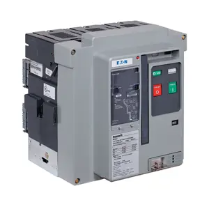
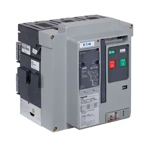
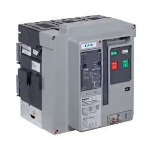
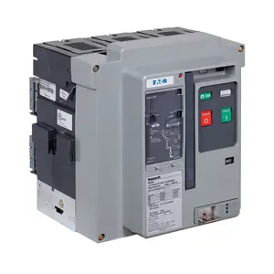
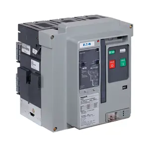
Eaton Power Circuit Breaker MDS-C08
Need answers fast?
Explore the manual using AI.
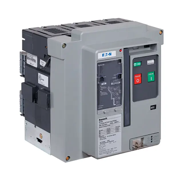
The Eaton Power Circuit Breaker MDS-C08 is a reliable and efficient circuit protection solution designed for industrial applications. This model ensures optimal performance and safety, featuring advanced trip mechanisms and robust construction to handle demanding electrical loads. Regular maintenance is essential to maximize its lifespan and functionality.
Turn manuals into instant answers
with your AI-powered assistantTurn manuals into instant answers
with your AI-powered assistant
Manual for Eaton Power Circuit Breaker MDS-C08
Complete asset maintenance, one click away
Get instant access to all the maintenance information you need. Empower technicians to perform preventive maintenance with asset packages, ready to use right out of the box.

Documents & Manuals
Find all the essential guides in one place.
 Tensioning Guide
- Belt-diagram
- C-120 pulleys
+ 13 more

Work Order Templates
Pre-built workflows to keep your asset running smoothly.
- Daily Electrical System Inspection
- Replace Roller and Pulley
- Install Engine B-120
+ 29 more

Procedures
Integrate maintenance plans directly into your work orders.
- Motion Industries
- Applied Industrial Technologies
- Electrical Brothers
+ 5 more

Parts
Access the parts list for your equipment in MaintainX.
- Drive Motor
- B2 Rollers
- Tensioning System
+ 40 more
Eaton Power Circuit Breaker MDS-C08
Create an account to install this asset package.
Maintenance Plans for Eaton Power Circuit Breaker Model MDS-C08
Integrate maintenance plans directly into your work orders in MaintainX.
1 Yearly Arc Chute Inspection
Pre-inspection conditions: Device(Fixed): Position of Poles: Open, Mechanism: Discharged, Device Position in Cassette: -. Device(Drawout): Position of Poles: Open, Mechanism: Discharged, Device Position in Cassette: Removed.
When a circuit breaker experiences a high-level fault or during regularly scheduled maintenance periods, the circuit breaker’s arc chutes and arc chambers should be inspected for any kind of damage or dirt. Be especially alert for signs of significant erosion of the V-shaped plated inside the arc chute.
Arc chutes fit inside the arc chambers and down over the primary contacts. Each arc chute is held in place by either 1 (SB) or 4 (SBSE) top inserted screws.
Remove arc chute screws and all arc chutes from the arc chamber.
Turn each arc chute upside down and visually inspect the inside.
Look for erosion and sooty discoloration on the splitter plates and insulating jacket. If arc chutes show severe signs of erosion or discoloration, replace with a new arc chute.
Note: Because the arc chutes are removed, this is an ideal time to inspect the primary contacts for wear (See Primary Contact Inspection procedure on page 59).
When the inspections are complete, position each arc chute over its respective set of primary contacts, and secure in place with the screw(s) removed earlier. Be sure to torque arc chute screws to 35 to 45 in-lb.
Sign off on the arc chute inspection

1 Yearly Primary Contact Inspection
Pre-inspection conditions: Device (Fixed): Position of Poles: Open, Mechanism: Discharged, Device Position in Cassette: -. Device (Drawout): Position of Poles: Open, Mechanism: Discharged, Device Position in Cassette: Removed.
Note: Using the mating line of the housing halves as a reference guide will assist in this visual inspection.
Remove the arc chutes, look directly down into the arc chamber (Figure 98), and visually inspect each primary contact structure for signs of wear and/or damage.
Use the contact wear indicator to inspect each contact The contact wear indicator is the relative position of the individual contact fingers to a narrow, side-to-side ledge inside the arc chamber The ledge is actually part of the arc chamber When the circuit breaker is closed and the contacts are in good condition, the narrow ledge is covered by the back end of each of the contact fingers (Figure 99) If the back end of any of the contacts are below the ledge, the contact assembly should be replaced.
Once the inspection is complete, be sure to verify the arc chutes are properly replaced as previously described in the Arc Chute Inspection procedure.
WARNING: ARC CHUTES MUST BE SECURED PROPERLY IN PLACE BEFORE A CIRCUIT BREAKER IS INSTALLED IN A CIRCUIT BREAKER COMPARTMENT. FAILURE TO DO THIS COULD RESULT IN EQUIPMENT DAMAGE, BODILY INJURY, OR EVEN DEATH.
Sign off on the inspection
2 Yearly Secondary Injection Trip Unit Testing
Warning: This procedure requires trained personnel!
Charged the breaker mechanism springs using the charging handle or the motor operator
Closed the breaker by applying rated voltage to the spring release accessory and verified closing by noting the state of the indicating flag
Charged the breaker mechanism springs again using the charging handle or the motor operator and disconnected power to prevent automatic recharging
Checked the state of the pop-out trip indicator and reset it if it was 'out'
Pressed the ON pushbutton to manually close the breaker and reset the indicator if it was 'out'
Used the Functional Test Kit to trip the breaker by setting its SELECT TEST switch to INST, then pressing its PUSH TO TEST button
Verified that the trip indicator pop-out button is 'out' and then reset it by pressing the pop-out button
Reset the trip unit by the Reset/Battery Test pushbutton on the front of the trip unit
3 Yearly Interlocks Inspection
Pre-Inspection Conditions: Device (Fixed): Position of Poles: Open, Mechanism: Discharged, Device Position in Cassette: -. Device (Drawout): Position of Poles: Open, Mechanism: Discharged, Device Position in Cassette: Removed.
WARNING: REMOVE THE DRAWOUT CIRCUIT BREAKERS FROM THE CASSETTE FOR THE FOLLOWING TESTS. FOR FIXED MOUNTED CIRCUIT BREAKERS, ALL PRIMARY AND SECONDARY POWER IS TO BE REMOVED.
Circuit breaker is in working order
Circuit breaker will not close if Undervoltage Release is NOT energized
Circuit breaker will not close if levering-in screw access door is open or not fully closed
Door does not close in intermediate positions
Circuit breaker will not close if OFF (open) pushbutton is depressed and then ON (close) pushbutton is depressed
Circuit breaker will not close if internal key lock is engaged
Key should not rotate fully and the breaker should remain in the closed position when key lock is disengaged
3 Yearly Internal Mechanism Inspection
Pre-inspection conditions:
Device (Fixed): Position of Poles: Open, Mechanism: Discharged, Device Position in Cassette: -.
Device (Drawout): Position of Poles: Open, Mechanism: Discharged, Device Position in Cassette: Removed.
Procedure:
1. Inspect the breaker for nicked wires, cracks in plastic parts, and loose screws Screws or bolts should be tightened to levels outlined in Table 22 Loose screws inserted into plastic parts will require thread-locking compound (such as Loctite 242) All nicked wiring should be replaced or repaired in accordance with accepted industry practices.
2. Ensure that the torque values of the operating mechanism and motor mounting hardware are within the recommended values in Table 18.
3. Inspect all sliding or rolling parts for cleanliness and adequate lubrication Refer to Table 23 and Figure 101—Figure 106.;
Unlock efficiency
with MaintainX CoPilot
MaintainX CoPilot is your expert colleague, on call 24/7, helping your team find the answers they need to keep equipment running.
'%20stroke-width='2.05034'/%3e%3cpath%20d='M43.601%2020.8897C43.2688%2019.252%2042.7312%2017.6627%2042.001%2016.1597'%20stroke='url(%23paint1_linear_4912_14668)'%20stroke-width='2.05034'/%3e%3cpath%20d='M40.001%2012.8882C38.8627%2011.3731%2037.516%2010.0265%2036.001%208.88818'%20stroke='url(%23paint2_linear_4912_14668)'%20stroke-width='2.05034'/%3e%3cpath%20d='M32.729%206.89053C31.2266%206.1604%2029.638%205.62282%2028.001%205.29053'%20stroke='url(%23paint3_linear_4912_14668)'%20stroke-width='2.05034'/%3e%3cpath%20d='M24.001%2014.8901V24.8901L32.001%2032.8901'%20stroke='url(%23paint4_linear_4912_14668)'%20stroke-width='2.05034'/%3e%3cdefs%3e%3clinearGradient%20id='paint0_linear_4912_14668'%20x1='4'%20y1='25'%20x2='44'%20y2='25'%20gradientUnits='userSpaceOnUse'%3e%3cstop%20stop-color='%23246CFF'/%3e%3cstop%20offset='1'%20stop-color='%232ED888'/%3e%3c/linearGradient%3e%3clinearGradient%20id='paint1_linear_4912_14668'%20x1='3.5'%20y1='20.8897'%20x2='44'%20y2='20.8897'%20gradientUnits='userSpaceOnUse'%3e%3cstop%20stop-color='%23246CFF'/%3e%3cstop%20offset='1'%20stop-color='%232ED888'/%3e%3c/linearGradient%3e%3clinearGradient%20id='paint2_linear_4912_14668'%20x1='3.5'%20y1='12.8882'%20x2='44.5'%20y2='12.8882'%20gradientUnits='userSpaceOnUse'%3e%3cstop%20stop-color='%23246CFF'/%3e%3cstop%20offset='1'%20stop-color='%232ED888'/%3e%3c/linearGradient%3e%3clinearGradient%20id='paint3_linear_4912_14668'%20x1='6.5'%20y1='6.89053'%20x2='43.5'%20y2='6.89053'%20gradientUnits='userSpaceOnUse'%3e%3cstop%20stop-color='%23246CFF'/%3e%3cstop%20offset='1'%20stop-color='%232ED888'/%3e%3c/linearGradient%3e%3clinearGradient%20id='paint4_linear_4912_14668'%20x1='5'%20y1='32.8901'%20x2='44'%20y2='32.8901'%20gradientUnits='userSpaceOnUse'%3e%3cstop%20stop-color='%23246CFF'/%3e%3cstop%20offset='1'%20stop-color='%232ED888'/%3e%3c/linearGradient%3e%3c/defs%3e%3c/svg%3e)
Reduce Unplanned Downtime
Ensure your team follows consistent procedures to minimize equipment failures and costly delays.
'%20stroke-width='2.05034'/%3e%3cpath%20d='M46.667%2041.7231C46.667%2044.5079%2045.5607%2047.1786%2043.5916%2049.1478C41.6225%2051.1169%2038.9518%2052.2231%2036.167%2052.2231C33.3822%2052.2231%2030.7115%2051.1169%2028.7424%2049.1478C26.7732%2047.1786%2025.667%2044.5079%2025.667%2041.7231C25.667%2038.9384%2026.7732%2036.2677%2028.7424%2034.2985C30.7115%2032.3294%2033.3822%2031.2231%2036.167%2031.2231C38.9518%2031.2231%2041.6225%2032.3294%2043.5916%2034.2985C45.5607%2036.2677%2046.667%2038.9384%2046.667%2041.7231Z'%20stroke='url(%23paint1_linear_4912_14680)'%20stroke-width='2.05034'/%3e%3cpath%20d='M37.334%2035.8896V40.5563H42.0007'%20stroke='url(%23paint2_linear_4912_14680)'%20stroke-width='2.05034'/%3e%3cdefs%3e%3clinearGradient%20id='paint0_linear_4912_14680'%20x1='5'%20y1='52.2231'%20x2='51'%20y2='52.2231'%20gradientUnits='userSpaceOnUse'%3e%3cstop%20stop-color='%23246CFF'/%3e%3cstop%20offset='1'%20stop-color='%232ED888'/%3e%3c/linearGradient%3e%3clinearGradient%20id='paint1_linear_4912_14680'%20x1='5'%20y1='52.2231'%20x2='47'%20y2='52.2231'%20gradientUnits='userSpaceOnUse'%3e%3cstop%20stop-color='%23246CFF'/%3e%3cstop%20offset='1'%20stop-color='%232ED888'/%3e%3c/linearGradient%3e%3clinearGradient%20id='paint2_linear_4912_14680'%20x1='5'%20y1='40.5563'%20x2='52.5'%20y2='40.5563'%20gradientUnits='userSpaceOnUse'%3e%3cstop%20stop-color='%23246CFF'/%3e%3cstop%20offset='1'%20stop-color='%232ED888'/%3e%3c/linearGradient%3e%3c/defs%3e%3c/svg%3e)
Maximize Asset Availability
Keep your assets running longer and more reliably, with standardized maintenance workflows from OEM manuals.
'%20stroke-width='2.05034'/%3e%3cpath%20d='M13.9995%2024.2231C13.9995%2029.1738%2015.9662%2033.9217%2019.4669%2037.4224C22.9675%2040.9231%2027.7155%2042.8897%2032.6662%2042.8897C37.6169%2042.8897%2042.3648%2040.9231%2045.8655%2037.4224C49.3662%2033.9217%2051.3328%2029.1738%2051.3328%2024.2231C51.3328%2019.2724%2049.3662%2014.5244%2045.8655%2011.0237C42.3648%207.52306%2037.6169%205.5564%2032.6662%205.5564C27.7155%205.5564%2022.9675%207.52306%2019.4669%2011.0237C15.9662%2014.5244%2013.9995%2019.2724%2013.9995%2024.2231Z'%20stroke='url(%23paint1_linear_4912_14674)'%20stroke-width='2.05034'/%3e%3cpath%20d='M32.6665%2017.2231V12.5564'%20stroke='url(%23paint2_linear_4912_14674)'%20stroke-width='2.05034'/%3e%3cpath%20d='M32.6665%2035.8898V31.2231'%20stroke='url(%23paint3_linear_4912_14674)'%20stroke-width='2.05034'/%3e%3cpath%20d='M37.9165%2020.7231V19.5565C37.9165%2018.9376%2037.6707%2018.3441%2037.2331%2017.9066C36.7955%2017.469%2036.202%2017.2231%2035.5832%2017.2231H29.7498C29.131%2017.2231%2028.5375%2017.469%2028.0999%2017.9066C27.6623%2018.3441%2027.4165%2018.9376%2027.4165%2019.5565V20.6018C27.4166%2021.1326%2027.5977%2021.6475%2027.9298%2022.0615C28.262%2022.4756%2028.7254%2022.764%2029.2435%2022.8791L36.0895%2024.4005C36.6077%2024.5157%2037.071%2024.8041%2037.4032%2025.2181C37.7353%2025.6321%2037.9164%2026.147%2037.9165%2026.6778V28.8898C37.9165%2029.5086%2037.6707%2030.1021%2037.2331%2030.5397C36.7955%2030.9773%2036.202%2031.2231%2035.5832%2031.2231H29.7498C29.131%2031.2231%2028.5375%2030.9773%2028.0999%2030.5397C27.6623%2030.1021%2027.4165%2029.5086%2027.4165%2028.8898V27.7231'%20stroke='url(%23paint4_linear_4912_14674)'%20stroke-width='2.05034'/%3e%3cdefs%3e%3clinearGradient%20id='paint0_linear_4912_14674'%20x1='5'%20y1='33.5'%20x2='50'%20y2='33.5'%20gradientUnits='userSpaceOnUse'%3e%3cstop%20stop-color='%23246CFF'/%3e%3cstop%20offset='1'%20stop-color='%232ED888'/%3e%3c/linearGradient%3e%3clinearGradient%20id='paint1_linear_4912_14674'%20x1='5'%20y1='42.8897'%20x2='48.5'%20y2='42.8897'%20gradientUnits='userSpaceOnUse'%3e%3cstop%20stop-color='%23246CFF'/%3e%3cstop%20offset='1'%20stop-color='%232ED888'/%3e%3c/linearGradient%3e%3clinearGradient%20id='paint2_linear_4912_14674'%20x1='5'%20y1='17.2231'%20x2='52.5'%20y2='17.2231'%20gradientUnits='userSpaceOnUse'%3e%3cstop%20stop-color='%23246CFF'/%3e%3cstop%20offset='1'%20stop-color='%232ED888'/%3e%3c/linearGradient%3e%3clinearGradient%20id='paint3_linear_4912_14674'%20x1='3.5'%20y1='35.8898'%20x2='50.5'%20y2='35.8898'%20gradientUnits='userSpaceOnUse'%3e%3cstop%20stop-color='%23246CFF'/%3e%3cstop%20offset='1'%20stop-color='%232ED888'/%3e%3c/linearGradient%3e%3clinearGradient%20id='paint4_linear_4912_14674'%20x1='3'%20y1='31.2231'%20x2='52'%20y2='31.2231'%20gradientUnits='userSpaceOnUse'%3e%3cstop%20stop-color='%23246CFF'/%3e%3cstop%20offset='1'%20stop-color='%232ED888'/%3e%3c/linearGradient%3e%3c/defs%3e%3c/svg%3e)
Lower Maintenance Costs
Turn any technician into an expert to streamline operations, maintain more assets, and reduce overall costs.
Thousands of companies manage their assets with MaintainX

'%3e%3cpath%20fill='url(%23b)'%20d='M66.008%2080.068c-5.084-.786-9.763-3.834-12.442-8.68a16.942%2016.942%200%200%201-1.87-5.18c1.096.19%202.203.476%203.298.87%206.525%202.333%2010.836%207.68%2011.014%2012.99ZM51.47%2061.576c.488-5.524%203.62-10.716%208.847-13.597a17.132%2017.132%200%200%201%2011.335-1.882c-.798%208.145-7.43%2014.848-16.038%2015.599-1.417.119-2.799.07-4.144-.12Zm28.564-11.478a17.513%2017.513%200%200%201%203.727%204.62c4.608%208.335%201.584%2018.813-6.75%2023.409a16.988%2016.988%200%200%201-4.359%201.679%2019.624%2019.624%200%200%201-3.977-12.776c.346-7.561%204.942-13.931%2011.36-16.932Z'/%3e%3cpath%20fill='%23110F0D'%20fill-rule='evenodd'%20d='M142.831%2048.324h4.977V77.03h-4.977V48.324Zm27.278%2013.002c.322%201.048.453%202.263.453%203.62v12.073h-4.787V66.208c0-.75-.047-1.572-.154-2.143-.453-2.382-1.822-3.572-4.215-3.572-2.31%200-3.882%201.274-4.43%203.476-.143.596-.226%201.405-.226%202.25v10.8h-4.787V56.623h4.477v2.989c1.536-2.5%203.906-3.43%206.371-3.43%203.488%200%206.263%201.68%207.298%205.144Zm24.636%207.323c0%203.882-2.358%206.525-5.763%207.727-1.298.453-2.632.643-4.62.643h-10.169V48.324h9.085c1.691%200%203.156.143%204.049.38%203.465.93%205.727%203.68%205.727%207.335%200%202.441-.81%204.156-2.762%205.644%202.905%201.417%204.453%203.727%204.453%206.966Zm-15.634-8.656h4.584c1.024%200%201.917-.143%202.536-.417%201.215-.548%201.905-1.608%201.905-3.167%200-1.548-.643-2.572-1.845-3.132-.691-.31-1.762-.452-2.763-.452h-4.417v7.168Zm10.716%208.465c0-1.536-.893-3.37-3.227-3.893-.428-.095-1.036-.143-1.571-.143h-5.918v8.085h5.501c.56%200%201.429-.048%201.953-.167%201.94-.453%203.262-1.846%203.262-3.882Zm47.747-11.847-8.097%2020.408h-4.429l-8.109-20.408h5.191l5.192%2014.574%205.108-14.574h5.144Zm-20.218%2010.002c0%20.69-.036%201.262-.155%201.94h-15.943c.631%202.87%202.714%204.728%205.882%204.728%202.131%200%203.607-.882%204.703-2.525h4.87c-1.762%204.144-5.204%206.692-9.657%206.692-6.084%200-10.537-4.858-10.537-10.49%200-6.108%204.524-10.776%2010.335-10.776%206.239%200%2010.442%204.954%2010.502%2010.43Zm-4.763-1.405c-.333-2.846-2.643-4.858-5.691-4.858-2.894%200-5.287%201.929-5.621%204.858h11.312Zm-72.667%203.44c0%204.787-3.287%208.371-9.419%208.371H119.363V64.66c-1.917.274-3.87.69-5.811%201.238l4.537%2011.121h-5.418l-3.596-9.585c-5.144%202.084-10.085%205.216-14.217%209.585h-4.786L101.8%2048.312h4.56l5.68%2013.883a44.112%2044.112%200%200%201%207.323-1.774V48.312h9.084c1.703%200%203.156.143%204.061.393%203.453.929%205.727%203.667%205.727%207.323%200%201.917-.738%204.179-2.81%205.691%203.06%201.56%204.501%204.025%204.501%206.93Zm-15.634-8.667a62.664%2062.664%200%200%201%202.06-.036c1.703.012%203.239.131%204.608.37%201.441-.549%202.357-1.727%202.357-3.537%200-1.941-.881-3.144-2.488-3.667-.548-.18-1.358-.286-2.322-.286h-4.215v7.156Zm-16.55%203.905-3.715-9.894-6.394%2016.502c2.833-2.595%206.263-4.858%2010.109-6.608Zm27.254%204.74c0-2.775-3.131-4.347-8.513-4.418-.715%200-1.441.011-2.191.047v8.252h5.918c2.548%200%204.786-1.37%204.786-3.882Z'%20clip-rule='evenodd'/%3e%3c/g%3e%3cdefs%3e%3clinearGradient%20id='b'%20x1='51.47'%20x2='85.916'%20y1='62.946'%20y2='62.946'%20gradientUnits='userSpaceOnUse'%3e%3cstop%20stop-color='%23CD9F28'/%3e%3cstop%20offset='1'%20stop-color='%23ECD80B'/%3e%3c/linearGradient%3e%3cclipPath%20id='a'%3e%3cpath%20fill='%23fff'%20d='M51.47%2045.728h186.104V80.14H51.47z'/%3e%3c/clipPath%3e%3c/defs%3e%3c/svg%3e)











More from Eaton
Explore Other Assets







© 2026 MaintainX. All rights reserved.