


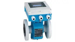
Daikin Heat Pump Outdoor Unit RXS15LVJU
Need answers fast?
Explore the manual using AI.
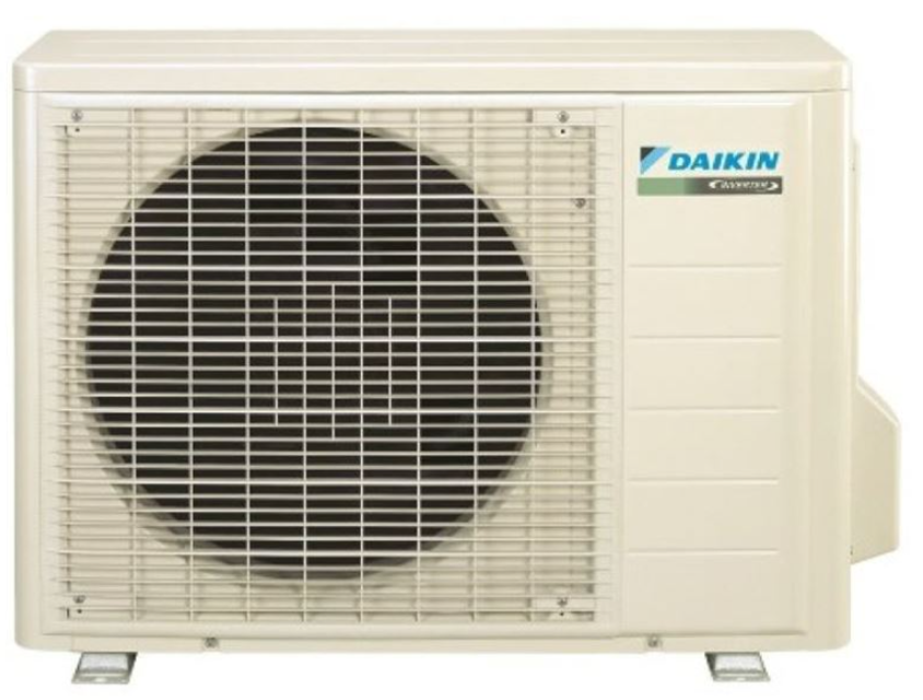
The Daikin Heat Pump Outdoor Unit RXS15LVJU is a high-efficiency heating and cooling solution designed for residential and commercial applications. With advanced technology and reliable performance, this unit ensures optimal climate control while minimizing energy consumption. Perfect for year-round comfort, it is a trusted choice for efficient heating and cooling needs.
Turn manuals into instant answers
with your AI-powered assistantTurn manuals into instant answers
with your AI-powered assistant
Manual for Daikin Heat Pump Outdoor Unit RXS15LVJU
Complete asset maintenance, one click away
Get instant access to all the maintenance information you need. Empower technicians to perform preventive maintenance with asset packages, ready to use right out of the box.

Documents & Manuals
Find all the essential guides in one place.
 Tensioning Guide
- Belt-diagram
- C-120 pulleys
+ 13 more

Work Order Templates
Pre-built workflows to keep your asset running smoothly.
- Daily Electrical System Inspection
- Replace Roller and Pulley
- Install Engine B-120
+ 29 more

Procedures
Integrate maintenance plans directly into your work orders.
- Motion Industries
- Applied Industrial Technologies
- Electrical Brothers
+ 5 more

Parts
Access the parts list for your equipment in MaintainX.
- Drive Motor
- B2 Rollers
- Tensioning System
+ 40 more
Daikin Heat Pump Outdoor Unit RXS15LVJU
Create an account to install this asset package.
Maintenance Plans for Daikin Heat Pump Outdoor Unit Model RXS15LVJU
Integrate maintenance plans directly into your work orders in MaintainX.
PCB Removal
Warning Be sure to wait for 10 minutes or more after turning off all power supplies before disassembling work.
1. Remove the main PCB.
1 Disconnect the connector [S12] and pull out the clamp.
[S12]: for [HL4] [HN4] on filter PCB
2 Disconnect the connector [S10].
[S10]: for [S11] on filter PCB
3 Pull out the clamp.
The compressor harness has a clamp.
When reassembling, insert the clamp as below.

Four-Way Valve Removal
Warning: Be sure to wait for 10 minutes or more after turning off all power supplies before disassembling work.
Remove the screw and remove the four-way valve coil.
Warning: Be careful not to get yourself burnt with the pipes and other parts that are heated by the gas brazing machine.
Warning: If the refrigerant gas leaks during work, ventilate the room. (If the refrigerant gas is exposed to flames, toxic gas may be generated.)
Caution: From the viewpoint of global environment protection, do not discharge the refrigerant gas in the atmosphere. Make sure to collect all the refrigerant gas.
Restore the piping by nonoxidation brazing.
It is required to prevent the carbonization of the oil inside the four-way valve and the deterioration of the gaskets affected by heat. (Keep below 120°C (248°F).) For the sake of this, wrap the four-way valve with wet cloth and provide water so that the cloth does not dry.
Never use a metal saw to cut pipes because the sawdust may enter the circuit.
When withdrawing the pipes, be careful not to pinch them firmly with pliers. The pipes may get deformed.
Electronic Expansion Valve Check
Warning: This check requires trained personnel with PPE!
EV connector correctly connected to the PCB
Did the EV generate a latching sound after power cycle?
Continuity confirmed using a tester after disconnecting the connector
Check the continuity between the pins
EV coil faulty if no continuity between the pins
Outdoor unit PCB faulty if continuity confirmed in step 3
Note: The latching sound varies depending on the valve type.
Sign off on the electronic expansion valve check
Thermistor Resistance Check
Warning: Disconnect the connectors of the thermistors from the PCB before proceeding
Thermistors disconnected from the PCB
Measure the resistance of each thermistor
Note: The relationship between normal temperature and resistance is shown in the table and the graph below
Display PCB removed from the control PCB
Measure the resistance of the room temperature thermistor
Indoor heat exchanger thermistor removed from the PCB
Measure the resistance of the indoor heat exchanger thermistor
Sign off on the thermistor resistance check
Service Check Function
Check Method 1
1. When the timer cancel button is held down for 5 seconds, 00 is displayed on the temperature display screen.
2. Press the timer cancel button repeatedly until a long beep sounds.
The code indication changes in the sequence shown below.
Note: 1. A short beep or two consecutive beeps indicate non-corresponding codes.
2. To return to the normal mode, hold the timer cancel button down for 5 seconds. When the remote controller is left untouched for 60 seconds, it also returns to the normal mode.
3. Not all the error codes are displayed. When you cannot find the error code, try the check method 2. (Refer to page 92.)
Check Method 2 1. Press the 3 buttons (TEMP, TEMP, MODE) at the same time to enter the diagnosis mode.
The left-side number blinks.
Parts for Daikin Heat Pump Outdoor Unit RXS15LVJU
Access the parts list for your equipment in MaintainX.
Silicon Grease
1172698
Inverter Checker
1225477
Silicon Grease
1172698
Inverter Checker
1225477
Silicon Grease
1172698
Inverter Checker
1225477
Unlock efficiency
with MaintainX CoPilot
MaintainX CoPilot is your expert colleague, on call 24/7, helping your team find the answers they need to keep equipment running.
Reduce Unplanned Downtime
Ensure your team follows consistent procedures to minimize equipment failures and costly delays.
Maximize Asset Availability
Keep your assets running longer and more reliably, with standardized maintenance workflows from OEM manuals.
Lower Maintenance Costs
Turn any technician into an expert to streamline operations, maintain more assets, and reduce overall costs.
Thousands of companies manage their assets with MaintainX

'%3e%3cpath%20fill='url(%23b)'%20d='M66.008%2080.068c-5.084-.786-9.763-3.834-12.442-8.68a16.942%2016.942%200%200%201-1.87-5.18c1.096.19%202.203.476%203.298.87%206.525%202.333%2010.836%207.68%2011.014%2012.99ZM51.47%2061.576c.488-5.524%203.62-10.716%208.847-13.597a17.132%2017.132%200%200%201%2011.335-1.882c-.798%208.145-7.43%2014.848-16.038%2015.599-1.417.119-2.799.07-4.144-.12Zm28.564-11.478a17.513%2017.513%200%200%201%203.727%204.62c4.608%208.335%201.584%2018.813-6.75%2023.409a16.988%2016.988%200%200%201-4.359%201.679%2019.624%2019.624%200%200%201-3.977-12.776c.346-7.561%204.942-13.931%2011.36-16.932Z'/%3e%3cpath%20fill='%23110F0D'%20fill-rule='evenodd'%20d='M142.831%2048.324h4.977V77.03h-4.977V48.324Zm27.278%2013.002c.322%201.048.453%202.263.453%203.62v12.073h-4.787V66.208c0-.75-.047-1.572-.154-2.143-.453-2.382-1.822-3.572-4.215-3.572-2.31%200-3.882%201.274-4.43%203.476-.143.596-.226%201.405-.226%202.25v10.8h-4.787V56.623h4.477v2.989c1.536-2.5%203.906-3.43%206.371-3.43%203.488%200%206.263%201.68%207.298%205.144Zm24.636%207.323c0%203.882-2.358%206.525-5.763%207.727-1.298.453-2.632.643-4.62.643h-10.169V48.324h9.085c1.691%200%203.156.143%204.049.38%203.465.93%205.727%203.68%205.727%207.335%200%202.441-.81%204.156-2.762%205.644%202.905%201.417%204.453%203.727%204.453%206.966Zm-15.634-8.656h4.584c1.024%200%201.917-.143%202.536-.417%201.215-.548%201.905-1.608%201.905-3.167%200-1.548-.643-2.572-1.845-3.132-.691-.31-1.762-.452-2.763-.452h-4.417v7.168Zm10.716%208.465c0-1.536-.893-3.37-3.227-3.893-.428-.095-1.036-.143-1.571-.143h-5.918v8.085h5.501c.56%200%201.429-.048%201.953-.167%201.94-.453%203.262-1.846%203.262-3.882Zm47.747-11.847-8.097%2020.408h-4.429l-8.109-20.408h5.191l5.192%2014.574%205.108-14.574h5.144Zm-20.218%2010.002c0%20.69-.036%201.262-.155%201.94h-15.943c.631%202.87%202.714%204.728%205.882%204.728%202.131%200%203.607-.882%204.703-2.525h4.87c-1.762%204.144-5.204%206.692-9.657%206.692-6.084%200-10.537-4.858-10.537-10.49%200-6.108%204.524-10.776%2010.335-10.776%206.239%200%2010.442%204.954%2010.502%2010.43Zm-4.763-1.405c-.333-2.846-2.643-4.858-5.691-4.858-2.894%200-5.287%201.929-5.621%204.858h11.312Zm-72.667%203.44c0%204.787-3.287%208.371-9.419%208.371H119.363V64.66c-1.917.274-3.87.69-5.811%201.238l4.537%2011.121h-5.418l-3.596-9.585c-5.144%202.084-10.085%205.216-14.217%209.585h-4.786L101.8%2048.312h4.56l5.68%2013.883a44.112%2044.112%200%200%201%207.323-1.774V48.312h9.084c1.703%200%203.156.143%204.061.393%203.453.929%205.727%203.667%205.727%207.323%200%201.917-.738%204.179-2.81%205.691%203.06%201.56%204.501%204.025%204.501%206.93Zm-15.634-8.667a62.664%2062.664%200%200%201%202.06-.036c1.703.012%203.239.131%204.608.37%201.441-.549%202.357-1.727%202.357-3.537%200-1.941-.881-3.144-2.488-3.667-.548-.18-1.358-.286-2.322-.286h-4.215v7.156Zm-16.55%203.905-3.715-9.894-6.394%2016.502c2.833-2.595%206.263-4.858%2010.109-6.608Zm27.254%204.74c0-2.775-3.131-4.347-8.513-4.418-.715%200-1.441.011-2.191.047v8.252h5.918c2.548%200%204.786-1.37%204.786-3.882Z'%20clip-rule='evenodd'/%3e%3c/g%3e%3cdefs%3e%3clinearGradient%20id='b'%20x1='51.47'%20x2='85.916'%20y1='62.946'%20y2='62.946'%20gradientUnits='userSpaceOnUse'%3e%3cstop%20stop-color='%23CD9F28'/%3e%3cstop%20offset='1'%20stop-color='%23ECD80B'/%3e%3c/linearGradient%3e%3cclipPath%20id='a'%3e%3cpath%20fill='%23fff'%20d='M51.47%2045.728h186.104V80.14H51.47z'/%3e%3c/clipPath%3e%3c/defs%3e%3c/svg%3e)


More from Daikin


Explore Other Assets


© 2026 MaintainX. All rights reserved.