


Daikin Cooling-only Outdoor Unit RKS30LVJU
Need answers fast?
Explore the manual using AI.
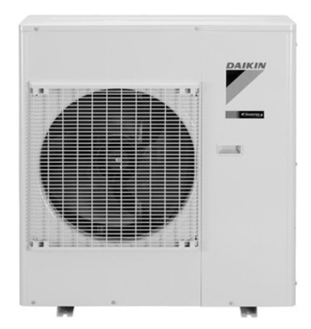
The Daikin Cooling-only Outdoor Unit RKS30LVJU is a reliable and efficient air conditioning solution designed for optimal cooling performance. Ideal for residential and commercial applications, this unit ensures consistent comfort while minimizing energy consumption. Experience superior cooling with Daikin's advanced technology and engineering.
Turn manuals into instant answers
with your AI-powered assistantTurn manuals into instant answers
with your AI-powered assistant
Manual for Daikin Cooling-only Outdoor Unit RKS30LVJU
Complete asset maintenance, one click away
Get instant access to all the maintenance information you need. Empower technicians to perform preventive maintenance with asset packages, ready to use right out of the box.

Documents & Manuals
Find all the essential guides in one place.
 Tensioning Guide
- Belt-diagram
- C-120 pulleys
+ 13 more

Work Order Templates
Pre-built workflows to keep your asset running smoothly.
- Daily Electrical System Inspection
- Replace Roller and Pulley
- Install Engine B-120
+ 29 more

Procedures
Integrate maintenance plans directly into your work orders.
- Motion Industries
- Applied Industrial Technologies
- Electrical Brothers
+ 5 more

Parts
Access the parts list for your equipment in MaintainX.
- Drive Motor
- B2 Rollers
- Tensioning System
+ 40 more
Daikin Cooling-only Outdoor Unit RKS30LVJU
Create an account to install this asset package.
Maintenance Plans for Daikin Cooling-only Outdoor Unit Model RKS30LVJU
Integrate maintenance plans directly into your work orders in MaintainX.
Sound Blanket Removal
Warning: Be sure to wait for 10 minutes or more after turning off all power supplies before disassembling work.
Open the sound blanket (outer)
Remove the sound blanket (top upper)
The sound blanket is fragile. Carefully pass the discharge pipe through it.
Remove the screw and slightly push the partition plate (1) to the left for easy work.
Remove the sound blanket (outer)
Open the sound blanket (inner)
Remove the sound blanket (inner)
The sound blanket is fragile. Be careful of the notches of the compressor mount (4 locations).

Outer Panel Removal
Warning Be sure to wait for 10 minutes or more after turning off all power supplies before disassembling work.
1. Appearance features.
2. Remove the suction grille.
The hooks are secured in the clearances of the outdoor heat exchanger fins.
1 Unfasten the 3 hooks at the upper first, and then 3 hooks at the middle.
2 Unfasten the 3 hooks at the bottom and remove the suction grille.
3. Remove the top panel.
1 Remove the 9 screws and remove the top panel.
4. Remove the right side panel.
Rotation Pulse Check
Check No.16 09/12 class
Voltage between the pins 10 - 11
Hall IC generates the rotation pulse 4 times between the pins 10 -12, 10 - 13, when the fan motor is manually rotated once
15/18/24/30/36 class
Voltage between the pins 4 - 7
Control voltage between the pins 3 - 4
Rotation command voltage between the pins 2 - 4
2 pulses are output at the pins 1 - 4 when the fan motor is rotated 1 turn by hand
When the fuse is melted, check the outdoor fan motor for proper function.
Service Check Function
Check Method 1
Timer cancel button held down for 5 seconds, 00 is displayed on the temperature display screen
Press the timer cancel button repeatedly until a long beep sounds
Note: A short beep or two consecutive beeps indicate non-corresponding codes
Return to the normal mode by holding the timer cancel button down for 5 seconds
Check Method 2
Press the 3 buttons (TEMP, TEMP, MODE) at the same time to enter the diagnosis mode
Press the [TEMP] or button and change the number until you hear the two consecutive beeps or the long beep
Press the [MODE] button
Power Supply Waveforms Check
Check No.11
Measure the power supply waveform between No. 1 and No. 2 on the terminal board
Check the waveform disturbance
Check to see if the power supply waveform is a sine wave
Check to see if there is waveform disturbance near the zero cross
Upload the waveform image
Sign off on the power supply waveforms check
Parts for Daikin Cooling-only Outdoor Unit RKS30LVJU
Access the parts list for your equipment in MaintainX.
Inverter Checker
1225477
Silicon Grease
1172698
Inverter Checker
1225477
Silicon Grease
1172698
Inverter Checker
1225477
Silicon Grease
1172698
Unlock efficiency
with MaintainX CoPilot
MaintainX CoPilot is your expert colleague, on call 24/7, helping your team find the answers they need to keep equipment running.
Reduce Unplanned Downtime
Ensure your team follows consistent procedures to minimize equipment failures and costly delays.
Maximize Asset Availability
Keep your assets running longer and more reliably, with standardized maintenance workflows from OEM manuals.
Lower Maintenance Costs
Turn any technician into an expert to streamline operations, maintain more assets, and reduce overall costs.
Thousands of companies manage their assets with MaintainX

'%3e%3cpath%20fill='url(%23b)'%20d='M66.008%2080.068c-5.084-.786-9.763-3.834-12.442-8.68a16.942%2016.942%200%200%201-1.87-5.18c1.096.19%202.203.476%203.298.87%206.525%202.333%2010.836%207.68%2011.014%2012.99ZM51.47%2061.576c.488-5.524%203.62-10.716%208.847-13.597a17.132%2017.132%200%200%201%2011.335-1.882c-.798%208.145-7.43%2014.848-16.038%2015.599-1.417.119-2.799.07-4.144-.12Zm28.564-11.478a17.513%2017.513%200%200%201%203.727%204.62c4.608%208.335%201.584%2018.813-6.75%2023.409a16.988%2016.988%200%200%201-4.359%201.679%2019.624%2019.624%200%200%201-3.977-12.776c.346-7.561%204.942-13.931%2011.36-16.932Z'/%3e%3cpath%20fill='%23110F0D'%20fill-rule='evenodd'%20d='M142.831%2048.324h4.977V77.03h-4.977V48.324Zm27.278%2013.002c.322%201.048.453%202.263.453%203.62v12.073h-4.787V66.208c0-.75-.047-1.572-.154-2.143-.453-2.382-1.822-3.572-4.215-3.572-2.31%200-3.882%201.274-4.43%203.476-.143.596-.226%201.405-.226%202.25v10.8h-4.787V56.623h4.477v2.989c1.536-2.5%203.906-3.43%206.371-3.43%203.488%200%206.263%201.68%207.298%205.144Zm24.636%207.323c0%203.882-2.358%206.525-5.763%207.727-1.298.453-2.632.643-4.62.643h-10.169V48.324h9.085c1.691%200%203.156.143%204.049.38%203.465.93%205.727%203.68%205.727%207.335%200%202.441-.81%204.156-2.762%205.644%202.905%201.417%204.453%203.727%204.453%206.966Zm-15.634-8.656h4.584c1.024%200%201.917-.143%202.536-.417%201.215-.548%201.905-1.608%201.905-3.167%200-1.548-.643-2.572-1.845-3.132-.691-.31-1.762-.452-2.763-.452h-4.417v7.168Zm10.716%208.465c0-1.536-.893-3.37-3.227-3.893-.428-.095-1.036-.143-1.571-.143h-5.918v8.085h5.501c.56%200%201.429-.048%201.953-.167%201.94-.453%203.262-1.846%203.262-3.882Zm47.747-11.847-8.097%2020.408h-4.429l-8.109-20.408h5.191l5.192%2014.574%205.108-14.574h5.144Zm-20.218%2010.002c0%20.69-.036%201.262-.155%201.94h-15.943c.631%202.87%202.714%204.728%205.882%204.728%202.131%200%203.607-.882%204.703-2.525h4.87c-1.762%204.144-5.204%206.692-9.657%206.692-6.084%200-10.537-4.858-10.537-10.49%200-6.108%204.524-10.776%2010.335-10.776%206.239%200%2010.442%204.954%2010.502%2010.43Zm-4.763-1.405c-.333-2.846-2.643-4.858-5.691-4.858-2.894%200-5.287%201.929-5.621%204.858h11.312Zm-72.667%203.44c0%204.787-3.287%208.371-9.419%208.371H119.363V64.66c-1.917.274-3.87.69-5.811%201.238l4.537%2011.121h-5.418l-3.596-9.585c-5.144%202.084-10.085%205.216-14.217%209.585h-4.786L101.8%2048.312h4.56l5.68%2013.883a44.112%2044.112%200%200%201%207.323-1.774V48.312h9.084c1.703%200%203.156.143%204.061.393%203.453.929%205.727%203.667%205.727%207.323%200%201.917-.738%204.179-2.81%205.691%203.06%201.56%204.501%204.025%204.501%206.93Zm-15.634-8.667a62.664%2062.664%200%200%201%202.06-.036c1.703.012%203.239.131%204.608.37%201.441-.549%202.357-1.727%202.357-3.537%200-1.941-.881-3.144-2.488-3.667-.548-.18-1.358-.286-2.322-.286h-4.215v7.156Zm-16.55%203.905-3.715-9.894-6.394%2016.502c2.833-2.595%206.263-4.858%2010.109-6.608Zm27.254%204.74c0-2.775-3.131-4.347-8.513-4.418-.715%200-1.441.011-2.191.047v8.252h5.918c2.548%200%204.786-1.37%204.786-3.882Z'%20clip-rule='evenodd'/%3e%3c/g%3e%3cdefs%3e%3clinearGradient%20id='b'%20x1='51.47'%20x2='85.916'%20y1='62.946'%20y2='62.946'%20gradientUnits='userSpaceOnUse'%3e%3cstop%20stop-color='%23CD9F28'/%3e%3cstop%20offset='1'%20stop-color='%23ECD80B'/%3e%3c/linearGradient%3e%3cclipPath%20id='a'%3e%3cpath%20fill='%23fff'%20d='M51.47%2045.728h186.104V80.14H51.47z'/%3e%3c/clipPath%3e%3c/defs%3e%3c/svg%3e)


More from Daikin


Explore Other Assets


© 2026 MaintainX. All rights reserved.