


'%3e%3cpath%20d='M10%2010.5V17h12.5v5.5l-21%20.038V15l8.5-4.5ZM1%206h11M6.5%202H12M5.5%2022.5V19'/%3e%3cpath%20d='M21.21%2017.012%2020.14%201.5h-4.28l-1.07%2015.512M15.516%206.49h4.967'/%3e%3c/g%3e%3cdefs%3e%3cclipPath%20id='a'%3e%3cpath%20fill='%23fff'%20d='M0%200h24v24H0z'/%3e%3c/clipPath%3e%3c/defs%3e%3c/svg%3e)











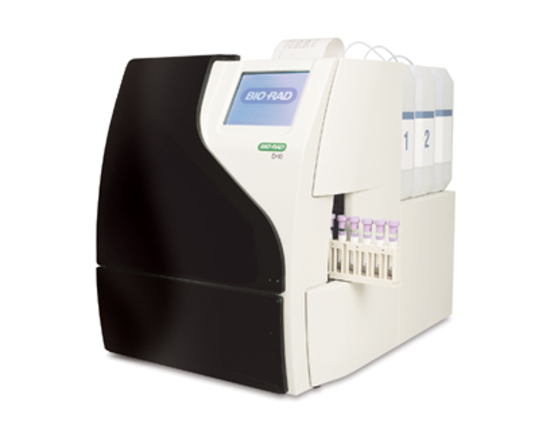
Bio-Rad Hemoglobin Testing System D10 DJ
Need answers fast?
Explore the manual using AI.
Turn manuals into instant answers
with your AI-powered assistantTurn manuals into instant answers
with your AI-powered assistant
Complete asset maintenance, one click away
Get instant access to all the maintenance information you need. Empower technicians to perform preventive maintenance with asset packages, ready to use right out of the box.

Documents & Manuals
Find all the essential guides in one place.
 Tensioning Guide
- Belt-diagram
- C-120 pulleys
+ 13 more

Work Order Templates
Pre-built workflows to keep your asset running smoothly.
- Daily Electrical System Inspection
- Replace Roller and Pulley
- Install Engine B-120
+ 29 more

Procedures
Integrate maintenance plans directly into your work orders.
- Motion Industries
- Applied Industrial Technologies
- Electrical Brothers
+ 5 more

Parts
Access the parts list for your equipment in MaintainX.
- Drive Motor
- B2 Rollers
- Tensioning System
+ 40 more
Bio-Rad Hemoglobin Testing System D10 DJ
Create an account to install this asset package.
Maintenance Plans for Bio-Rad Hemoglobin Testing System Model D10 DJ
Integrate maintenance plans directly into your work orders in MaintainX.
Hemoglobin Testing System ATX Power Supply Replacement
Remove the Electronics Module and Power Supply cover
Release the Cable Anchor and remove the Power Supply output connector from the Power Board CN5
Remove two mounting screws from each side of the supply
Remove the supply and lay it upside down on the work bench
Remove the four screws holding the mounting bracket to the bottom of the supply
Install the mounting bracket on the new supply
Ensure screws are not overly tightened
Fasten the Power Supply to the Module with the four screws removed earlier
Connect Power Supply Output Connector CN5 to the Power Board

Power Surge Protection Board Replacement
1) Perform steps 1 through 7 in 4.2.4 above:
1. Remove the Printer from the plastic housing. There are no fasteners, the printer lifts up from the front.
2. Disconnect Power and Communication cables from the rear of the printer and lift the Printer from the instrument.
3. Remove the Top Cover. Loosen the two half turn fasteners. Slide the cover to the rear and lift to remove.
4. Remove the Right side door from the instrument.
5. Loosen the half turn fastener from the Buffer tray side cover. Lift the cover and remove it from the instrument.
6. Loosen the two Knurled fasteners in the lower corners of the supply module cover. The one on the right can be accessed with a Philips screw driver as shown. The left fastener can be unscrewed by hand or right angle Philips driver. If the fastener is overly tight the Syringe module can be removed to gain access.
7. The cover is attached at the top with two pins. Lift the cover up to clear the attachment pins and out of the instrument.
8. Remove the three Power Supply Connectors then the four mounting screws, one in each corner. Remove the supply from the instrument.
Touch Screen Board Replacement
1. Open the Right and Left Side doors. Perform steps 2 and 3 to remove the front cover.
2. Disconnect the two cables connected to the board.
3. Remove the two 2mm hex head screws fastening the board to the module bracket.
4. Installation is the reverse of the steps above.;
Hemoglobin Testing System Motherboard Replacement
Preparation
Ensure you have a long handle 2.5 mm Hex Head Driver
Place a piece of paper under the Electronic Module to catch any dropped screws
Motherboard Removal
Remove all cables from the CPU Motherboard
Remove the 9 fastening screws securing the board to the Electronic Assembly using a 2.5 mm Hex Head Driver
Remove the two Rack Loader port connector standoff posts from the rear of the instrument
Slide the board towards the front of the instrument and remove it from the rear
Motherboard Installation
Hemoglobin Testing System Display Replacement
1. Open the Right and Left Side doors. Perform steps 2 and 3 of Section 4.3.1 to remove the front cover.
2. Release the cables from the anchor closest to the display. Disconnect the Communication cable from the Touch Screen Driver board.
3. Remove the four screws holding the Display to the Display Chassis Bracket. Remove the cable from the Display Board. Remove the Display from the instrument.
4. Place the Display face down on the work surface. The Touch Screen Flex Cable attached to the Display has a White Mylar side and a conductor side. The external cable connected to the Flex cable is not keyed. Mark the external cable to show which side is connected to the White side of the Flex Circuit cable. Disconnect the External Cable from the Flex Cable.
5. Connect the External cable removed in step 4 to the Flex Cable on the replacement display. Connect so that the White side of the Flex Cable connection corresponds with the mark placed on the cable in step 4.
6. Install the Display Board connector removed in step 3. Attach the display to the Module Bracket with the four mounting screws.
7. Perform steps 1 and 2 in reverse to connect the display and install the Front and Side covers.;
Parts for Bio-Rad Hemoglobin Testing System D10 DJ
Access the parts list for your equipment in MaintainX.
Kyospeed 2 Printer
2200664
Printer Mounting Tray
2200646
Sata Hard Drive
2200662
DVD RW Drive
2200663
USB Port
2200658
Kyospeed 2 Printer
2200664
Printer Mounting Tray
2200646
Sata Hard Drive
2200662
DVD RW Drive
2200663
USB Port
2200658
Kyospeed 2 Printer
2200664
Printer Mounting Tray
2200646
Sata Hard Drive
2200662
DVD RW Drive
2200663
USB Port
2200658
Unlock
efficiency with MaintainX Assist
MaintainX Assist is your expert colleague, on call 24/7, helping your team find the answers they need to keep equipment running.
'/%3e%3cpath%20d='M32.0001%2048.6663C22.7953%2048.6663%2015.3335%2041.2043%2015.3335%2031.9997C15.3335%2022.7949%2022.7954%2015.333%2032.0001%2015.333C39.463%2015.333%2045.7096%2020.2378%2047.8335%2026.9997H43.6668'%20stroke='white'%20stroke-width='2.85714'%20stroke-linecap='round'%20stroke-linejoin='round'/%3e%3cpath%20d='M32%2025.333V31.9997L35.3333%2035.333'%20stroke='white'%20stroke-width='2.85714'%20stroke-linecap='round'%20stroke-linejoin='round'/%3e%3cpath%20d='M48.5918%2033.6667C48.6413%2033.1182%2048.6667%2032.5622%2048.6667%2032M37%2048.6667C37.5693%2048.4793%2038.1255%2048.2607%2038.6667%2048.013M46.651%2040.3333C46.9725%2039.714%2047.2592%2039.0722%2047.5083%2038.4103M42.3208%2045.7153C42.8948%2045.2402%2043.4385%2044.7263%2043.948%2044.1775'%20stroke='white'%20stroke-width='2.85714'%20stroke-linecap='round'%20stroke-linejoin='round'/%3e%3cdefs%3e%3clinearGradient%20id='paint0_linear_9036_2820'%20x1='17.4188'%20y1='24.2718'%20x2='46.9529'%20y2='57.2957'%20gradientUnits='userSpaceOnUse'%3e%3cstop%20stop-color='%23246CFF'/%3e%3cstop%20offset='1'%20stop-color='%2321C779'/%3e%3c/linearGradient%3e%3c/defs%3e%3c/svg%3e)
Reduce Unplanned Downtime
Ensure your team follows consistent procedures to minimize equipment failures and costly delays.
'/%3e%3cpath%20d='M15.7599%2038.0533C15.8165%2037.5147%2016.2068%2037.0805%2016.9875%2036.2123L18.706%2034.2912C19.126%2033.7593%2019.4241%2032.833%2019.4241%2031.9993C19.4241%2031.1663%2019.1259%2030.2397%2018.7059%2029.708L16.9875%2027.7869C16.2068%2026.9186%2015.8164%2026.4845%2015.7599%2025.9458C15.7033%2025.4071%2015.9949%2024.9011%2016.578%2023.889L17.4007%2022.4613C18.0228%2021.3816%2018.3339%2020.8417%2018.8632%2020.6265C19.3925%2020.4112%2019.9911%2020.5811%2021.1883%2020.9208L23.2221%2021.4936C23.9864%2021.6699%2024.7883%2021.5699%2025.4862%2021.2113L26.0477%2020.8874C26.6462%2020.504%2027.1065%2019.9389%2027.3613%2019.2746L27.9179%2017.6122C28.2839%2016.5122%2028.4668%2015.9622%2028.9024%2015.6476C29.3381%2015.333%2029.9167%2015.333%2031.0739%2015.333H32.9319C34.0892%2015.333%2034.6679%2015.333%2035.1034%2015.6476C35.5391%2015.9622%2035.7221%2016.5122%2036.0881%2017.6122L36.6446%2019.2746C36.8994%2019.9389%2037.3597%2020.504%2037.9582%2020.8874L38.5197%2021.2113C39.2176%2021.5699%2040.0196%2021.6699%2040.7839%2021.4936L42.8176%2020.9208C44.0147%2020.5811%2044.6134%2020.4112%2045.1427%2020.6265C45.6721%2020.8417%2045.9831%2021.3816%2046.6052%2022.4613L47.4279%2023.889C48.0111%2024.9011%2048.3026%2025.4071%2048.2461%2025.9458C48.1894%2026.4845%2047.7991%2026.9186%2047.0184%2027.7869L45.2999%2029.708C44.8801%2030.2397%2044.5817%2031.1663%2044.5817%2031.9993C44.5817%2032.833%2044.8799%2033.7593%2045.2999%2034.2912L47.0184%2036.2123C47.7991%2037.0805%2048.1894%2037.5147%2048.2461%2038.0533C48.3026%2038.5922%2048.0111%2039.0982%2047.4279%2040.1102L46.6052%2041.5378C45.9831%2042.6175%2045.6721%2043.1575%2045.1427%2043.3727C44.6134%2043.588%2044.0147%2043.4182%2042.8176%2043.0783L40.7839%2042.5055C40.0194%2042.3292%2039.2174%2042.4293%2038.5194%2042.788L37.9581%2043.112C37.3596%2043.4953%2036.8994%2044.0603%2036.6447%2044.7247L36.0881%2046.3872C35.7221%2047.4872%2035.5391%2048.0372%2035.1034%2048.3517C34.6679%2048.6663%2034.0892%2048.6663%2032.9319%2048.6663H31.0739C29.9167%2048.6663%2029.3381%2048.6663%2028.9024%2048.3517C28.4668%2048.0372%2028.2839%2047.4872%2027.9179%2046.3872'%20stroke='white'%20stroke-width='2.85714'%20stroke-linecap='round'/%3e%3cpath%20d='M16.5614%2043.2993C18.3614%2041.4993%2024.4814%2035.4393%2025.0814%2034.7393C25.7157%2033.9993%2025.2014%2032.9993%2025.5074%2029.8993C25.6555%2028.3993%2025.9781%2027.2756%2026.9014%2026.4393C28.0014%2025.3993%2028.9015%2025.3993%2032.0015%2025.3294C34.7015%2025.3993%2035.0215%2025.0993%2035.3015%2025.7994C35.5015%2026.2994%2034.9015%2026.5993%2034.1815%2027.3994C32.5815%2028.9993%2031.6415%2029.7993%2031.5515%2030.2993C30.9015%2032.4993%2033.4615%2033.7993%2034.8615%2032.3993C35.3908%2031.8698%2037.8415%2029.3993%2038.0815%2029.1993C38.2615%2029.0393%2038.6923%2029.047%2038.9015%2029.2993C39.0815%2029.4762%2039.1015%2029.4993%2039.0815%2030.2993C39.063%2031.0398%2039.0712%2032.103%2039.0735%2033.1993C39.0763%2034.6198%2039.0015%2036.1993%2038.4015%2036.9993C37.2015%2038.7993%2035.2015%2038.8993%2033.4015%2038.9793C31.7015%2039.0793%2030.3015%2038.8993%2029.8615%2039.2193C29.5015%2039.3993%2027.6014%2041.3993%2025.3014%2043.6993L21.2014%2047.7993C17.8014%2050.4993%2014.0614%2046.2993%2016.5614%2043.2993Z'%20stroke='white'%20stroke-width='2.85714'%20stroke-linecap='round'/%3e%3cdefs%3e%3clinearGradient%20id='paint0_linear_9036_2840'%20x1='17.4188'%20y1='24.2718'%20x2='46.9529'%20y2='57.2957'%20gradientUnits='userSpaceOnUse'%3e%3cstop%20stop-color='%23246CFF'/%3e%3cstop%20offset='1'%20stop-color='%2321C779'/%3e%3c/linearGradient%3e%3c/defs%3e%3c/svg%3e)
Maximize Asset Availability
Keep your assets running longer and more reliably, with standardized maintenance workflows from OEM manuals.
'/%3e%3cpath%20d='M35.3333%2041.9997C42.6972%2041.9997%2048.6667%2036.0302%2048.6667%2028.6663C48.6667%2021.3025%2042.6972%2015.333%2035.3333%2015.333C27.9695%2015.333%2022%2021.3025%2022%2028.6663C22%2036.0302%2027.9695%2041.9997%2035.3333%2041.9997Z'%20stroke='white'%20stroke-width='2.85714'%20stroke-linecap='round'/%3e%3cpath%20d='M17.2611%2030.333C16.0422%2032.1957%2015.3335%2034.4222%2015.3335%2036.8143C15.3335%2043.36%2020.6398%2048.6663%2027.1854%2048.6663C29.5777%2048.6663%2031.8042%2047.9577%2033.6668%2046.7387'%20stroke='white'%20stroke-width='2.85714'%20stroke-linecap='round'/%3e%3cpath%20d='M38.2854%2025.6752C37.9251%2024.155%2036.0911%2022.7832%2033.8896%2023.8095C31.6881%2024.8357%2031.3384%2028.1376%2034.6684%2028.4884C36.1736%2028.647%2037.1548%2028.3044%2038.0533%2029.2733C38.9516%2030.2422%2039.1186%2032.9365%2036.8219%2033.6627C34.5253%2034.3888%2032.2511%2033.2542%2032.0034%2031.6432M35.3104%2022.0068V23.4552M35.3104%2033.8862V35.3402'%20stroke='white'%20stroke-width='2.85714'%20stroke-linecap='round'%20stroke-linejoin='round'/%3e%3cdefs%3e%3clinearGradient%20id='paint0_linear_9036_2830'%20x1='17.4188'%20y1='24.2718'%20x2='46.9529'%20y2='57.2957'%20gradientUnits='userSpaceOnUse'%3e%3cstop%20stop-color='%23246CFF'/%3e%3cstop%20offset='1'%20stop-color='%2321C779'/%3e%3c/linearGradient%3e%3c/defs%3e%3c/svg%3e)
Lower Maintenance Costs
Turn any technician into an expert to streamline operations, maintain more assets, and reduce overall costs.
Thousands of companies manage their assets with MaintainX

'%3e%3cpath%20fill='url(%23b)'%20d='M66.008%2080.068c-5.084-.786-9.763-3.834-12.442-8.68a16.942%2016.942%200%200%201-1.87-5.18c1.096.19%202.203.476%203.298.87%206.525%202.333%2010.836%207.68%2011.014%2012.99ZM51.47%2061.576c.488-5.524%203.62-10.716%208.847-13.597a17.132%2017.132%200%200%201%2011.335-1.882c-.798%208.145-7.43%2014.848-16.038%2015.599-1.417.119-2.799.07-4.144-.12Zm28.564-11.478a17.513%2017.513%200%200%201%203.727%204.62c4.608%208.335%201.584%2018.813-6.75%2023.409a16.988%2016.988%200%200%201-4.359%201.679%2019.624%2019.624%200%200%201-3.977-12.776c.346-7.561%204.942-13.931%2011.36-16.932Z'/%3e%3cpath%20fill='%23110F0D'%20fill-rule='evenodd'%20d='M142.831%2048.324h4.977V77.03h-4.977V48.324Zm27.278%2013.002c.322%201.048.453%202.263.453%203.62v12.073h-4.787V66.208c0-.75-.047-1.572-.154-2.143-.453-2.382-1.822-3.572-4.215-3.572-2.31%200-3.882%201.274-4.43%203.476-.143.596-.226%201.405-.226%202.25v10.8h-4.787V56.623h4.477v2.989c1.536-2.5%203.906-3.43%206.371-3.43%203.488%200%206.263%201.68%207.298%205.144Zm24.636%207.323c0%203.882-2.358%206.525-5.763%207.727-1.298.453-2.632.643-4.62.643h-10.169V48.324h9.085c1.691%200%203.156.143%204.049.38%203.465.93%205.727%203.68%205.727%207.335%200%202.441-.81%204.156-2.762%205.644%202.905%201.417%204.453%203.727%204.453%206.966Zm-15.634-8.656h4.584c1.024%200%201.917-.143%202.536-.417%201.215-.548%201.905-1.608%201.905-3.167%200-1.548-.643-2.572-1.845-3.132-.691-.31-1.762-.452-2.763-.452h-4.417v7.168Zm10.716%208.465c0-1.536-.893-3.37-3.227-3.893-.428-.095-1.036-.143-1.571-.143h-5.918v8.085h5.501c.56%200%201.429-.048%201.953-.167%201.94-.453%203.262-1.846%203.262-3.882Zm47.747-11.847-8.097%2020.408h-4.429l-8.109-20.408h5.191l5.192%2014.574%205.108-14.574h5.144Zm-20.218%2010.002c0%20.69-.036%201.262-.155%201.94h-15.943c.631%202.87%202.714%204.728%205.882%204.728%202.131%200%203.607-.882%204.703-2.525h4.87c-1.762%204.144-5.204%206.692-9.657%206.692-6.084%200-10.537-4.858-10.537-10.49%200-6.108%204.524-10.776%2010.335-10.776%206.239%200%2010.442%204.954%2010.502%2010.43Zm-4.763-1.405c-.333-2.846-2.643-4.858-5.691-4.858-2.894%200-5.287%201.929-5.621%204.858h11.312Zm-72.667%203.44c0%204.787-3.287%208.371-9.419%208.371H119.363V64.66c-1.917.274-3.87.69-5.811%201.238l4.537%2011.121h-5.418l-3.596-9.585c-5.144%202.084-10.085%205.216-14.217%209.585h-4.786L101.8%2048.312h4.56l5.68%2013.883a44.112%2044.112%200%200%201%207.323-1.774V48.312h9.084c1.703%200%203.156.143%204.061.393%203.453.929%205.727%203.667%205.727%207.323%200%201.917-.738%204.179-2.81%205.691%203.06%201.56%204.501%204.025%204.501%206.93Zm-15.634-8.667a62.664%2062.664%200%200%201%202.06-.036c1.703.012%203.239.131%204.608.37%201.441-.549%202.357-1.727%202.357-3.537%200-1.941-.881-3.144-2.488-3.667-.548-.18-1.358-.286-2.322-.286h-4.215v7.156Zm-16.55%203.905-3.715-9.894-6.394%2016.502c2.833-2.595%206.263-4.858%2010.109-6.608Zm27.254%204.74c0-2.775-3.131-4.347-8.513-4.418-.715%200-1.441.011-2.191.047v8.252h5.918c2.548%200%204.786-1.37%204.786-3.882Z'%20clip-rule='evenodd'/%3e%3c/g%3e%3cdefs%3e%3clinearGradient%20id='b'%20x1='51.47'%20x2='85.916'%20y1='62.946'%20y2='62.946'%20gradientUnits='userSpaceOnUse'%3e%3cstop%20stop-color='%23CD9F28'/%3e%3cstop%20offset='1'%20stop-color='%23ECD80B'/%3e%3c/linearGradient%3e%3cclipPath%20id='a'%3e%3cpath%20fill='%23fff'%20d='M51.47%2045.728h186.104V80.14H51.47z'/%3e%3c/clipPath%3e%3c/defs%3e%3c/svg%3e)











More from Bio-Rad
Explore Other Assets



© 2026 MaintainX. All rights reserved.