


Baker Hughes Safety Relief Valves 1900/1900 DM Series
Need answers fast?
Explore the manual using AI.
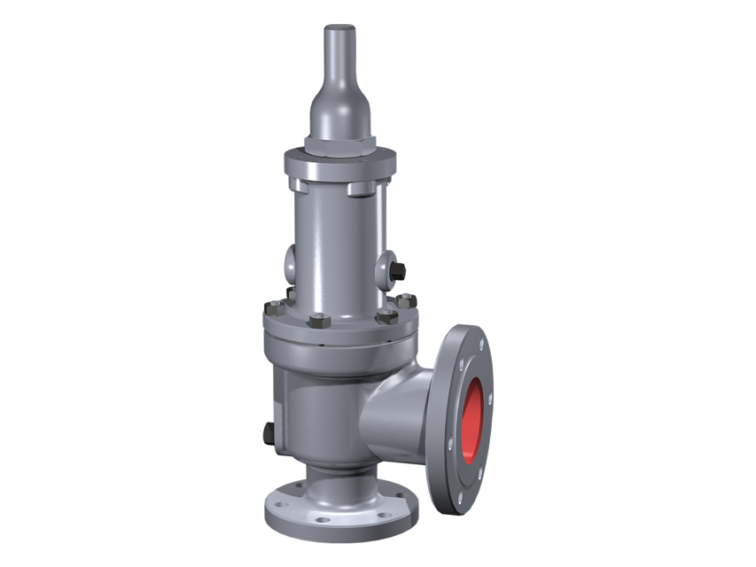
Baker Hughes Safety Relief Valves, specifically the 1900/1900 DM Series, are essential components designed to protect industrial systems from overpressure conditions. These valves ensure safety and reliability in various applications, making them a critical asset for effective pressure management in industrial environments.
Turn manuals into instant answers
with your AI-powered assistantTurn manuals into instant answers
with your AI-powered assistant
Manual for Baker Hughes Safety Relief Valves 1900/1900 DM Series
Complete asset maintenance, one click away
Get instant access to all the maintenance information you need. Empower technicians to perform preventive maintenance with asset packages, ready to use right out of the box.

Documents & Manuals
Find all the essential guides in one place.
 Tensioning Guide
- Belt-diagram
- C-120 pulleys
+ 13 more

Work Order Templates
Pre-built workflows to keep your asset running smoothly.
- Daily Electrical System Inspection
- Replace Roller and Pulley
- Install Engine B-120
+ 29 more

Procedures
Integrate maintenance plans directly into your work orders.
- Motion Industries
- Applied Industrial Technologies
- Electrical Brothers
+ 5 more

Parts
Access the parts list for your equipment in MaintainX.
- Drive Motor
- B2 Rollers
- Tensioning System
+ 40 more
Baker Hughes Safety Relief Valves 1900/1900 DM Series
Create an account to install this asset package.
Maintenance Plans for Baker Hughes Safety Relief Valves Model 1900/1900 DM Series
Integrate maintenance plans directly into your work orders in MaintainX.
1900 Series Cryodisc Replacement Criteria
The Cryodisc must be replaced if: - Seat defects and damage cannot be lapped out without reducing the A dimension below those listed in Table 7 (see Figure 34).
- ATTENTION! The A dimension on orifice D through H of the thermal lip disc is difficult to measure.
- If the .006" (0.15 mm) minimum thickness of the thermal lip cannot be measured, replace the Thermodisc.
- The A dimension on orifice D through H of the cryogenic disc is also difficult to measure.
- If the .008" (0.19 mm) (D, E, F orifice), .009" (0.23 mm) (G orifice), or .011" (0.27 mm) (H orifice) minimum thickness of the cryogenic disc lip cannot be measured, replace the Cryodisc.

Nozzle Inspection Criteria
Nozzle should be replaced if: - Dimension from seat to first thread, after re-machining and lapping, is less than D min. (see Tables 3)
- Threads are damaged from pitting and/or corrosion
- Top of flange and intersecting surface are damaged from galling and/or tearing
- Seat width is outside specification and cannot be reestablished per Nozzle Dimensions in Table 3a & 3c (see Tables 3a, 3b or 3c).
1900 Series SRV Standard Disc Inspection Areas
- The standard 1900 Series disc can be machined until the N dimension is reduced to its minimum size (see Table 5).
- The T dimension is provided to ensure the disc has not been machined beyond its limits.
- If re-machining reduces the thickness of the disc (T min.), the entire disc holder assembly drops with respect to the seating plane of the nozzle.
- This creates a significant change in the huddle chamber configuration and results in significantly more simmer before opening.;
Nozzle Seat Width Inspection
- Using a measuring magnifying glass (see Lapped Nozzle Seat Widths), determine whether the seating surface must be machined before lapping.
- If the seat can be lapped flat without exceeding the required seat width (see Tables 1a, 1b or 1c), it does not require machining.
- To reduce the seat width, the 5º angle surface must be machined and all seat dimensions need to be verified, and reestablished if necessary.
- The nozzle must be replaced if the D dimension is reduced below the minimum (see Tables 3).
- ATTENTION! Flange thickness changes the center-to-face dimension. Ensure the minimum dimension for orifice D through P is .656" (16.67 mm), and for Q through W is .797" (20.24 mm).;
Guide Inspection Criteria
Replace the guide (9) if: - Visible galling is present on the inside guiding surface
Gasket seating areas are pitted and cause the valve to leak between the bonnet (11) and base (1).
- The guide (9) type varies depending on the valve type: O-ring valve, bellows valve, or standard valve.
- Inspect the guide as follows: Find the correct valve orifice size and disc holder (8) measurements (see Table 9)
- Measure the barrel portion of the disc holder and compare it to the nominal measurement on Table 6 to determine the maximum allowable clearance between the disc holder and the guide
- Replace the guide and disc holder if the clearance between the inner diameter (I.D) and the guide and/or the outer diameter (O.D) of the disc holder is not within the clearance dimensions.;
Parts for Baker Hughes Safety Relief Valves 1900/1900 DM Series
Access the parts list for your equipment in MaintainX.
O-Ring Seat Seal
55
Bottom Plate
-
Soft Seat (DA) Disc Retainer
1900 DM
O-Ring Retainer
-
Base
1
O-Ring Seat Seal
55
Bottom Plate
-
Soft Seat (DA) Disc Retainer
1900 DM
O-Ring Retainer
-
Base
1
O-Ring Seat Seal
55
Bottom Plate
-
Soft Seat (DA) Disc Retainer
1900 DM
O-Ring Retainer
-
Base
1
Unlock efficiency
with MaintainX CoPilot
MaintainX CoPilot is your expert colleague, on call 24/7, helping your team find the answers they need to keep equipment running.
Reduce Unplanned Downtime
Ensure your team follows consistent procedures to minimize equipment failures and costly delays.
Maximize Asset Availability
Keep your assets running longer and more reliably, with standardized maintenance workflows from OEM manuals.
Lower Maintenance Costs
Turn any technician into an expert to streamline operations, maintain more assets, and reduce overall costs.
Thousands of companies manage their assets with MaintainX

'%3e%3cpath%20fill='url(%23b)'%20d='M66.008%2080.068c-5.084-.786-9.763-3.834-12.442-8.68a16.942%2016.942%200%200%201-1.87-5.18c1.096.19%202.203.476%203.298.87%206.525%202.333%2010.836%207.68%2011.014%2012.99ZM51.47%2061.576c.488-5.524%203.62-10.716%208.847-13.597a17.132%2017.132%200%200%201%2011.335-1.882c-.798%208.145-7.43%2014.848-16.038%2015.599-1.417.119-2.799.07-4.144-.12Zm28.564-11.478a17.513%2017.513%200%200%201%203.727%204.62c4.608%208.335%201.584%2018.813-6.75%2023.409a16.988%2016.988%200%200%201-4.359%201.679%2019.624%2019.624%200%200%201-3.977-12.776c.346-7.561%204.942-13.931%2011.36-16.932Z'/%3e%3cpath%20fill='%23110F0D'%20fill-rule='evenodd'%20d='M142.831%2048.324h4.977V77.03h-4.977V48.324Zm27.278%2013.002c.322%201.048.453%202.263.453%203.62v12.073h-4.787V66.208c0-.75-.047-1.572-.154-2.143-.453-2.382-1.822-3.572-4.215-3.572-2.31%200-3.882%201.274-4.43%203.476-.143.596-.226%201.405-.226%202.25v10.8h-4.787V56.623h4.477v2.989c1.536-2.5%203.906-3.43%206.371-3.43%203.488%200%206.263%201.68%207.298%205.144Zm24.636%207.323c0%203.882-2.358%206.525-5.763%207.727-1.298.453-2.632.643-4.62.643h-10.169V48.324h9.085c1.691%200%203.156.143%204.049.38%203.465.93%205.727%203.68%205.727%207.335%200%202.441-.81%204.156-2.762%205.644%202.905%201.417%204.453%203.727%204.453%206.966Zm-15.634-8.656h4.584c1.024%200%201.917-.143%202.536-.417%201.215-.548%201.905-1.608%201.905-3.167%200-1.548-.643-2.572-1.845-3.132-.691-.31-1.762-.452-2.763-.452h-4.417v7.168Zm10.716%208.465c0-1.536-.893-3.37-3.227-3.893-.428-.095-1.036-.143-1.571-.143h-5.918v8.085h5.501c.56%200%201.429-.048%201.953-.167%201.94-.453%203.262-1.846%203.262-3.882Zm47.747-11.847-8.097%2020.408h-4.429l-8.109-20.408h5.191l5.192%2014.574%205.108-14.574h5.144Zm-20.218%2010.002c0%20.69-.036%201.262-.155%201.94h-15.943c.631%202.87%202.714%204.728%205.882%204.728%202.131%200%203.607-.882%204.703-2.525h4.87c-1.762%204.144-5.204%206.692-9.657%206.692-6.084%200-10.537-4.858-10.537-10.49%200-6.108%204.524-10.776%2010.335-10.776%206.239%200%2010.442%204.954%2010.502%2010.43Zm-4.763-1.405c-.333-2.846-2.643-4.858-5.691-4.858-2.894%200-5.287%201.929-5.621%204.858h11.312Zm-72.667%203.44c0%204.787-3.287%208.371-9.419%208.371H119.363V64.66c-1.917.274-3.87.69-5.811%201.238l4.537%2011.121h-5.418l-3.596-9.585c-5.144%202.084-10.085%205.216-14.217%209.585h-4.786L101.8%2048.312h4.56l5.68%2013.883a44.112%2044.112%200%200%201%207.323-1.774V48.312h9.084c1.703%200%203.156.143%204.061.393%203.453.929%205.727%203.667%205.727%207.323%200%201.917-.738%204.179-2.81%205.691%203.06%201.56%204.501%204.025%204.501%206.93Zm-15.634-8.667a62.664%2062.664%200%200%201%202.06-.036c1.703.012%203.239.131%204.608.37%201.441-.549%202.357-1.727%202.357-3.537%200-1.941-.881-3.144-2.488-3.667-.548-.18-1.358-.286-2.322-.286h-4.215v7.156Zm-16.55%203.905-3.715-9.894-6.394%2016.502c2.833-2.595%206.263-4.858%2010.109-6.608Zm27.254%204.74c0-2.775-3.131-4.347-8.513-4.418-.715%200-1.441.011-2.191.047v8.252h5.918c2.548%200%204.786-1.37%204.786-3.882Z'%20clip-rule='evenodd'/%3e%3c/g%3e%3cdefs%3e%3clinearGradient%20id='b'%20x1='51.47'%20x2='85.916'%20y1='62.946'%20y2='62.946'%20gradientUnits='userSpaceOnUse'%3e%3cstop%20stop-color='%23CD9F28'/%3e%3cstop%20offset='1'%20stop-color='%23ECD80B'/%3e%3c/linearGradient%3e%3cclipPath%20id='a'%3e%3cpath%20fill='%23fff'%20d='M51.47%2045.728h186.104V80.14H51.47z'/%3e%3c/clipPath%3e%3c/defs%3e%3c/svg%3e)


More from Baker Hughes


Explore Other Assets


© 2026 MaintainX. All rights reserved.