


Baker Hughes Clamp-On Tag Flowmeter CTF878
Need answers fast?
Explore the manual using AI.
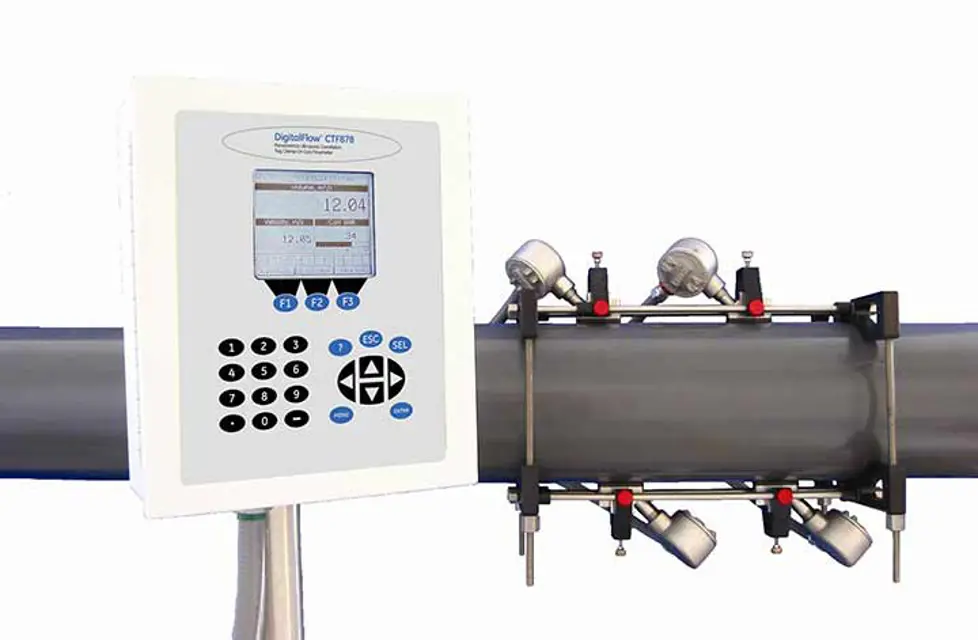
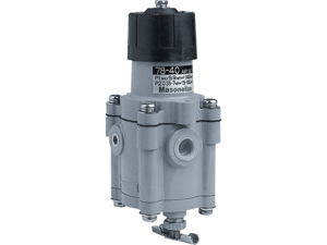
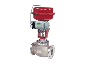
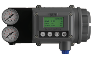
The Baker Hughes Clamp-On Tag Flowmeter CTF878 is a highly accurate and reliable flow measurement solution designed for various industrial applications. This advanced flowmeter offers easy installation and maintenance, ensuring optimal performance and longevity in demanding environments.
Turn manuals into instant answers
with your AI-powered assistantTurn manuals into instant answers
with your AI-powered assistant
Manual for Baker Hughes Clamp-On Tag Flowmeter CTF878
Complete asset maintenance, one click away
Get instant access to all the maintenance information you need. Empower technicians to perform preventive maintenance with asset packages, ready to use right out of the box.

Documents & Manuals
Find all the essential guides in one place.
 Tensioning Guide
- Belt-diagram
- C-120 pulleys
+ 13 more

Work Order Templates
Pre-built workflows to keep your asset running smoothly.
- Daily Electrical System Inspection
- Replace Roller and Pulley
- Install Engine B-120
+ 29 more

Procedures
Integrate maintenance plans directly into your work orders.
- Motion Industries
- Applied Industrial Technologies
- Electrical Brothers
+ 5 more

Parts
Access the parts list for your equipment in MaintainX.
- Drive Motor
- B2 Rollers
- Tensioning System
+ 40 more
Baker Hughes Clamp-On Tag Flowmeter CTF878
Create an account to install this asset package.
Maintenance Plans for Baker Hughes Clamp-On Tag Flowmeter Model CTF878
Integrate maintenance plans directly into your work orders in MaintainX.
Option Card Replacement
1. Remove the printed circuit board, as described previously.
2. Place the printed circuit board face down on a clean, flat surface.
3. If one or more option cards are already installed, remove the four fasteners that secure the metal bracket to the printed circuit board. Lift the metal bracket straight up and away from the printed circuit board.
4. Insert the 32-pin connector of the option card into any available option card socket (J41-J46) on the rear of the printed circuit board. Gently press the card into place, ensuring the pins in the connector are straight and properly aligned with the socket.
5. Repeat the above step to install any additional option cards.
6. Place the metal bracket over the option cards, ensuring all option cards are aligned with the plastic card guides in the bracket. Secure the metal bracket to the printed circuit board with the snap rivets provided.;

LCD Display Replacement
1. Open the cover on the electronics console.
2. Disconnect the white-ribbon display cable from connector J7, open the two cable brackets (inside the enclosure and on the inside surface of the cover), and free the display cable.
3. Using a 3/16 inch nutdriver, remove the four nut/washer sets that secure the display shroud to the inside of the console cover. Lift the display shroud off its mounting studs.
4. Using a 1/4" nutdriver, remove the four standoffs that secure the LCD display assembly to the console cover. Lift the LCD display assembly off its mounting studs.
5. Place the new LCD display assembly over the mounting studs on the console cover (in the same orientation as the one being replaced) and secure it with the four standoffs.
6. Install the display shroud over the mounting studs with the bent edges on the top and bottom extending toward the cover.
7. Fasten the display shroud to the console cover with the four sets of nuts and washers.
8. Feed the white-ribbon display cable through the cable brackets, close the brackets, and connect the cable to connector J7.;
Fuse Replacement
1. Open the cover on the electronics console. Remove the two mounting screws and lift the clear plastic shroud out of the electronics console.
2. Locate the black plastic fuse holder that is mounted on the printed circuit board between the power terminal block TB1 and the RS232 terminal block. The fuse holder extends below the main aluminum shroud, and the fuse holder cap is located on the bottom of the fuse holder.
3. Using a small standard screwdriver, turn the fuse holder cap counterclockwise about 1/4 turn. The fuse holder cap, with the captive fuse, will be ejected from the fuse holder.
4. Replace the defective fuse with a new one of the same rating and type. Use only 1-1/4" x 1/4" Slo-Blo fuses, having a rating as indicated in Table 1 and on the wiring diagram label.
5. Press the new fuse into the fuse holder cap and insert the fuse into the fuse holder. While applying a slight pressure with the screwdriver, twist the fuse holder cap 1/4" turn clockwise.
6. Place the clear plastic shroud over the standoffs in the electronics console and secure it in place with its two mounting screws. Close the cover on the electronics console.
The CTF878 flowmeter may now be placed back into service. Reconnect the main power and resume taking measurements.;
Printed Circuit Board Replacement
Removing the Printed Circuit Board
1. Remove the main power to the electronics console.
2. Open the electronics console. Remove the two mounting screws and lift the clear plastic shroud out of the electronics console. Remove the five mounting screws and lift the main aluminum shroud out of the electronics console.
3. Disconnect the main power leads from terminal block TB1 on the printed circuit board. Remove the electrical connections from all installed option cards and terminal blocks. Disconnect the twisted-pair backlight cable from connector J6, the two striped-ribbon keyboard cables from connector J5, and the white-ribbon display cable from connector J7.
4. Using a Phillips screwdriver and a 3/8 inch nutdriver or open-end wrench, remove the three mounting screws (just left of center) and the five standoffs along the sides of the main circuit board.
5. While supporting the printed circuit board, remove the two standoffs along the bottom edge of the printed circuit board.
6. Carefully lift the printed circuit board out of the enclosure.
CAUTION: During this procedure, be very careful not to damage the upright components along the top edge of the printed circuit board. Severe or repeated bending of these components will break their leads.
Installing the Printed Circuit Board
Parts for Baker Hughes Clamp-On Tag Flowmeter CTF878
Access the parts list for your equipment in MaintainX.
Conduit Plate
421-700
Option Card
703-1127-02
Main Printed Circuit Board
703-1344-02
Fuse Cap
215-018
Conduit Plate
421-702
Conduit Plate
421-700
Option Card
703-1127-02
Main Printed Circuit Board
703-1344-02
Fuse Cap
215-018
Conduit Plate
421-702
Conduit Plate
421-700
Option Card
703-1127-02
Main Printed Circuit Board
703-1344-02
Fuse Cap
215-018
Conduit Plate
421-702
Unlock efficiency
with MaintainX CoPilot
MaintainX CoPilot is your expert colleague, on call 24/7, helping your team find the answers they need to keep equipment running.
Reduce Unplanned Downtime
Ensure your team follows consistent procedures to minimize equipment failures and costly delays.
Maximize Asset Availability
Keep your assets running longer and more reliably, with standardized maintenance workflows from OEM manuals.
Lower Maintenance Costs
Turn any technician into an expert to streamline operations, maintain more assets, and reduce overall costs.
Thousands of companies manage their assets with MaintainX

'%3e%3cpath%20fill='url(%23b)'%20d='M66.008%2080.068c-5.084-.786-9.763-3.834-12.442-8.68a16.942%2016.942%200%200%201-1.87-5.18c1.096.19%202.203.476%203.298.87%206.525%202.333%2010.836%207.68%2011.014%2012.99ZM51.47%2061.576c.488-5.524%203.62-10.716%208.847-13.597a17.132%2017.132%200%200%201%2011.335-1.882c-.798%208.145-7.43%2014.848-16.038%2015.599-1.417.119-2.799.07-4.144-.12Zm28.564-11.478a17.513%2017.513%200%200%201%203.727%204.62c4.608%208.335%201.584%2018.813-6.75%2023.409a16.988%2016.988%200%200%201-4.359%201.679%2019.624%2019.624%200%200%201-3.977-12.776c.346-7.561%204.942-13.931%2011.36-16.932Z'/%3e%3cpath%20fill='%23110F0D'%20fill-rule='evenodd'%20d='M142.831%2048.324h4.977V77.03h-4.977V48.324Zm27.278%2013.002c.322%201.048.453%202.263.453%203.62v12.073h-4.787V66.208c0-.75-.047-1.572-.154-2.143-.453-2.382-1.822-3.572-4.215-3.572-2.31%200-3.882%201.274-4.43%203.476-.143.596-.226%201.405-.226%202.25v10.8h-4.787V56.623h4.477v2.989c1.536-2.5%203.906-3.43%206.371-3.43%203.488%200%206.263%201.68%207.298%205.144Zm24.636%207.323c0%203.882-2.358%206.525-5.763%207.727-1.298.453-2.632.643-4.62.643h-10.169V48.324h9.085c1.691%200%203.156.143%204.049.38%203.465.93%205.727%203.68%205.727%207.335%200%202.441-.81%204.156-2.762%205.644%202.905%201.417%204.453%203.727%204.453%206.966Zm-15.634-8.656h4.584c1.024%200%201.917-.143%202.536-.417%201.215-.548%201.905-1.608%201.905-3.167%200-1.548-.643-2.572-1.845-3.132-.691-.31-1.762-.452-2.763-.452h-4.417v7.168Zm10.716%208.465c0-1.536-.893-3.37-3.227-3.893-.428-.095-1.036-.143-1.571-.143h-5.918v8.085h5.501c.56%200%201.429-.048%201.953-.167%201.94-.453%203.262-1.846%203.262-3.882Zm47.747-11.847-8.097%2020.408h-4.429l-8.109-20.408h5.191l5.192%2014.574%205.108-14.574h5.144Zm-20.218%2010.002c0%20.69-.036%201.262-.155%201.94h-15.943c.631%202.87%202.714%204.728%205.882%204.728%202.131%200%203.607-.882%204.703-2.525h4.87c-1.762%204.144-5.204%206.692-9.657%206.692-6.084%200-10.537-4.858-10.537-10.49%200-6.108%204.524-10.776%2010.335-10.776%206.239%200%2010.442%204.954%2010.502%2010.43Zm-4.763-1.405c-.333-2.846-2.643-4.858-5.691-4.858-2.894%200-5.287%201.929-5.621%204.858h11.312Zm-72.667%203.44c0%204.787-3.287%208.371-9.419%208.371H119.363V64.66c-1.917.274-3.87.69-5.811%201.238l4.537%2011.121h-5.418l-3.596-9.585c-5.144%202.084-10.085%205.216-14.217%209.585h-4.786L101.8%2048.312h4.56l5.68%2013.883a44.112%2044.112%200%200%201%207.323-1.774V48.312h9.084c1.703%200%203.156.143%204.061.393%203.453.929%205.727%203.667%205.727%207.323%200%201.917-.738%204.179-2.81%205.691%203.06%201.56%204.501%204.025%204.501%206.93Zm-15.634-8.667a62.664%2062.664%200%200%201%202.06-.036c1.703.012%203.239.131%204.608.37%201.441-.549%202.357-1.727%202.357-3.537%200-1.941-.881-3.144-2.488-3.667-.548-.18-1.358-.286-2.322-.286h-4.215v7.156Zm-16.55%203.905-3.715-9.894-6.394%2016.502c2.833-2.595%206.263-4.858%2010.109-6.608Zm27.254%204.74c0-2.775-3.131-4.347-8.513-4.418-.715%200-1.441.011-2.191.047v8.252h5.918c2.548%200%204.786-1.37%204.786-3.882Z'%20clip-rule='evenodd'/%3e%3c/g%3e%3cdefs%3e%3clinearGradient%20id='b'%20x1='51.47'%20x2='85.916'%20y1='62.946'%20y2='62.946'%20gradientUnits='userSpaceOnUse'%3e%3cstop%20stop-color='%23CD9F28'/%3e%3cstop%20offset='1'%20stop-color='%23ECD80B'/%3e%3c/linearGradient%3e%3cclipPath%20id='a'%3e%3cpath%20fill='%23fff'%20d='M51.47%2045.728h186.104V80.14H51.47z'/%3e%3c/clipPath%3e%3c/defs%3e%3c/svg%3e)


More from Baker Hughes


Explore Other Assets


© 2026 MaintainX. All rights reserved.