


Baker Hughes Pneumatic Positioners 4700P/4800P
Need answers fast?
Explore the manual using AI.
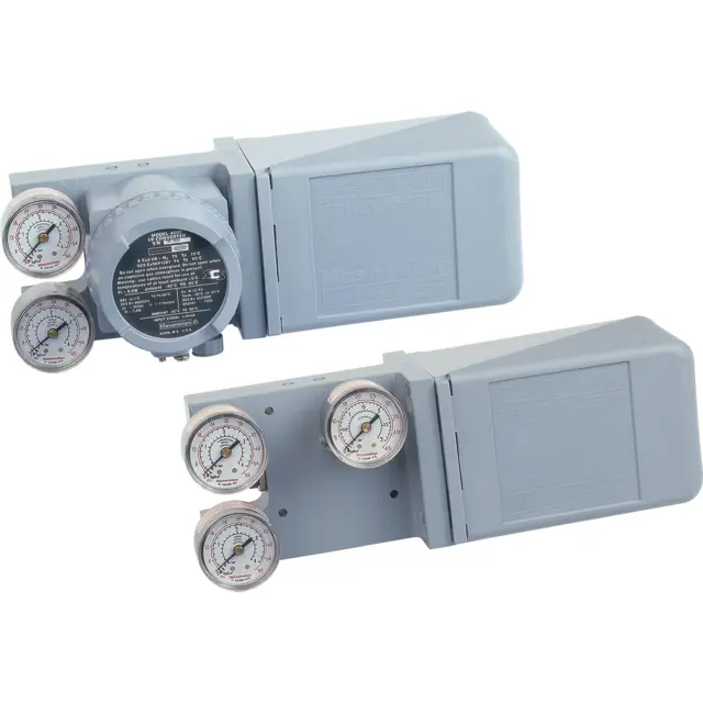
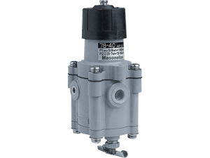
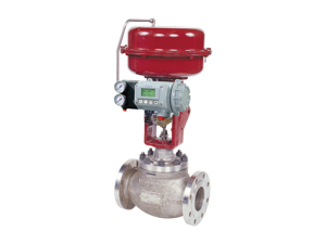
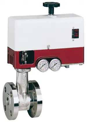
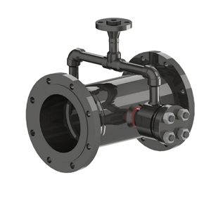
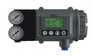
Baker Hughes Pneumatic Positioners, models 4700P and 4800P, are essential components in industrial automation, providing precise control of valve positions. These reliable positioners enhance system efficiency and accuracy, making them ideal for various applications in process industries. Regular maintenance ensures optimal performance and longevity.
Turn manuals into instant answers
with your AI-powered assistantTurn manuals into instant answers
with your AI-powered assistant
Manual for Baker Hughes Pneumatic Positioners 4700P/4800P
Complete asset maintenance, one click away
Get instant access to all the maintenance information you need. Empower technicians to perform preventive maintenance with asset packages, ready to use right out of the box.

Documents & Manuals
Find all the essential guides in one place.
 Tensioning Guide
- Belt-diagram
- C-120 pulleys
+ 13 more

Work Order Templates
Pre-built workflows to keep your asset running smoothly.
- Daily Electrical System Inspection
- Replace Roller and Pulley
- Install Engine B-120
+ 29 more

Procedures
Integrate maintenance plans directly into your work orders.
- Motion Industries
- Applied Industrial Technologies
- Electrical Brothers
+ 5 more

Parts
Access the parts list for your equipment in MaintainX.
- Drive Motor
- B2 Rollers
- Tensioning System
+ 40 more
Baker Hughes Pneumatic Positioners 4700P/4800P
Create an account to install this asset package.
Maintenance Plans for Baker Hughes Pneumatic Positioners Model 4700P/4800P
Integrate maintenance plans directly into your work orders in MaintainX.
Diaphragm Replacement
- If the diaphragm has deteriorated, replace the diaphragm assembly. This requires separation of the body and case subassemblies as outlined under.;

Body Maintenance
- Shut off the air supply. Disconnect air lines, linkage if reciprocating, and electrical connections if 4700E/4800E. If positioner is reverse acting, refer to applicable section under “Cam Lobe Change” on page 38 to safely remove cam. Remove screw (28), washer (27), cam (26). Separate positioner from actuator by removing screws (29) and washers (30).
Disassembly
See Figure 18 (page 56) and Figure 19 (page 58).
1. Remove pressure gauges (12) (13), and on 4700P/4800P only (14).
2. Remove the pilot subassembly (11).
3. Remove retaining ring (17), washer (16), lever S/A (3), and spring (5).
4. On 4700E/4800E only, remove 4 screws (21) to separate I/P module from body.
5. Remove cap screws (10) and separate body S/A from the case S/A.
6. Remove the diaphragm assembly (9), and reducer plate if 6-30 psi range 4700P/4800P.
Bypass Valve Option Maintenance (4700P Only)
Assembly to Positioner
- It may be necessary to remove positioner from valve to assemble bypass.
1. Remove air connections, vent plug, and instrument gauge.
2. Clean surface of body and remove any thread sealant left in threaded ports.
3. Install O-rings (50) in each of the four recesses on the rear surface of the module (45), making sure they are seated in the bottom of the recess.
4. Assemble to positioner using four 8-32 x 1.25” long screws (21).
5. Reinstall vent plug, instrument gauge, and air connections.
Disassembly
1. To remove from positioner, reverse assembly steps 5 and 4.
Pilot Maintenance
- To clean or replace deteriorated parts, the valve must be isolated from process. Shut off air supply. To minimize maintenance time, it is recommended that the entire pilot subassembly (11) be replaced by a new subassembly, so that the old unit can be worked on when time permits.
Disassembly 1. Unscrew the pilot subassembly (11) and disengage it from the body (1). Note: Turn the pilot subassembly while removing it to prevent damage to the O-rings.
2. Remove end plug and withdraw the spring, plug and extension pin. If necessary, use a penetrating oil to free parts.
3. Wipe the parts with a clean soft lint free cloth and blow compressed air through the orifices. Use isopropyl alcohol to clean. Do not use chloride based solvents.
Reassembly
1. Install three new O-rings on the pilot spool. Put a light coating of silicone grease on each O-ring.
2. Replace the extension pin and the plug, countersunk end first into the pilot spool. The plug should slide into the pilot spool by its own weight.
3. Install the spring in the pilot spool. The end having the smallest diameter must be in contact with the plug. Screw the pilot end plug into the pilot spool.
4. Install the pilot subassembly (11) into the body (1).;
I/P Module Replacement
- Replacement of the I/P module requires removal of electrical connections, including conduit if used. Remove positioner from valve if module mounting screws are not accessible. Remove and replace module as outlined under.;
Parts for Baker Hughes Pneumatic Positioners 4700P/4800P
Access the parts list for your equipment in MaintainX.
Clamp
-
Truarc Ring
-
Spring, Feedback
-
Socket Head Screw
-
Pilot S/A
-
Clamp
-
Truarc Ring
-
Spring, Feedback
-
Socket Head Screw
-
Pilot S/A
-
Clamp
-
Truarc Ring
-
Spring, Feedback
-
Socket Head Screw
-
Pilot S/A
-
Unlock efficiency
with MaintainX CoPilot
MaintainX CoPilot is your expert colleague, on call 24/7, helping your team find the answers they need to keep equipment running.
Reduce Unplanned Downtime
Ensure your team follows consistent procedures to minimize equipment failures and costly delays.
Maximize Asset Availability
Keep your assets running longer and more reliably, with standardized maintenance workflows from OEM manuals.
Lower Maintenance Costs
Turn any technician into an expert to streamline operations, maintain more assets, and reduce overall costs.
Thousands of companies manage their assets with MaintainX

'%3e%3cpath%20fill='url(%23b)'%20d='M66.008%2080.068c-5.084-.786-9.763-3.834-12.442-8.68a16.942%2016.942%200%200%201-1.87-5.18c1.096.19%202.203.476%203.298.87%206.525%202.333%2010.836%207.68%2011.014%2012.99ZM51.47%2061.576c.488-5.524%203.62-10.716%208.847-13.597a17.132%2017.132%200%200%201%2011.335-1.882c-.798%208.145-7.43%2014.848-16.038%2015.599-1.417.119-2.799.07-4.144-.12Zm28.564-11.478a17.513%2017.513%200%200%201%203.727%204.62c4.608%208.335%201.584%2018.813-6.75%2023.409a16.988%2016.988%200%200%201-4.359%201.679%2019.624%2019.624%200%200%201-3.977-12.776c.346-7.561%204.942-13.931%2011.36-16.932Z'/%3e%3cpath%20fill='%23110F0D'%20fill-rule='evenodd'%20d='M142.831%2048.324h4.977V77.03h-4.977V48.324Zm27.278%2013.002c.322%201.048.453%202.263.453%203.62v12.073h-4.787V66.208c0-.75-.047-1.572-.154-2.143-.453-2.382-1.822-3.572-4.215-3.572-2.31%200-3.882%201.274-4.43%203.476-.143.596-.226%201.405-.226%202.25v10.8h-4.787V56.623h4.477v2.989c1.536-2.5%203.906-3.43%206.371-3.43%203.488%200%206.263%201.68%207.298%205.144Zm24.636%207.323c0%203.882-2.358%206.525-5.763%207.727-1.298.453-2.632.643-4.62.643h-10.169V48.324h9.085c1.691%200%203.156.143%204.049.38%203.465.93%205.727%203.68%205.727%207.335%200%202.441-.81%204.156-2.762%205.644%202.905%201.417%204.453%203.727%204.453%206.966Zm-15.634-8.656h4.584c1.024%200%201.917-.143%202.536-.417%201.215-.548%201.905-1.608%201.905-3.167%200-1.548-.643-2.572-1.845-3.132-.691-.31-1.762-.452-2.763-.452h-4.417v7.168Zm10.716%208.465c0-1.536-.893-3.37-3.227-3.893-.428-.095-1.036-.143-1.571-.143h-5.918v8.085h5.501c.56%200%201.429-.048%201.953-.167%201.94-.453%203.262-1.846%203.262-3.882Zm47.747-11.847-8.097%2020.408h-4.429l-8.109-20.408h5.191l5.192%2014.574%205.108-14.574h5.144Zm-20.218%2010.002c0%20.69-.036%201.262-.155%201.94h-15.943c.631%202.87%202.714%204.728%205.882%204.728%202.131%200%203.607-.882%204.703-2.525h4.87c-1.762%204.144-5.204%206.692-9.657%206.692-6.084%200-10.537-4.858-10.537-10.49%200-6.108%204.524-10.776%2010.335-10.776%206.239%200%2010.442%204.954%2010.502%2010.43Zm-4.763-1.405c-.333-2.846-2.643-4.858-5.691-4.858-2.894%200-5.287%201.929-5.621%204.858h11.312Zm-72.667%203.44c0%204.787-3.287%208.371-9.419%208.371H119.363V64.66c-1.917.274-3.87.69-5.811%201.238l4.537%2011.121h-5.418l-3.596-9.585c-5.144%202.084-10.085%205.216-14.217%209.585h-4.786L101.8%2048.312h4.56l5.68%2013.883a44.112%2044.112%200%200%201%207.323-1.774V48.312h9.084c1.703%200%203.156.143%204.061.393%203.453.929%205.727%203.667%205.727%207.323%200%201.917-.738%204.179-2.81%205.691%203.06%201.56%204.501%204.025%204.501%206.93Zm-15.634-8.667a62.664%2062.664%200%200%201%202.06-.036c1.703.012%203.239.131%204.608.37%201.441-.549%202.357-1.727%202.357-3.537%200-1.941-.881-3.144-2.488-3.667-.548-.18-1.358-.286-2.322-.286h-4.215v7.156Zm-16.55%203.905-3.715-9.894-6.394%2016.502c2.833-2.595%206.263-4.858%2010.109-6.608Zm27.254%204.74c0-2.775-3.131-4.347-8.513-4.418-.715%200-1.441.011-2.191.047v8.252h5.918c2.548%200%204.786-1.37%204.786-3.882Z'%20clip-rule='evenodd'/%3e%3c/g%3e%3cdefs%3e%3clinearGradient%20id='b'%20x1='51.47'%20x2='85.916'%20y1='62.946'%20y2='62.946'%20gradientUnits='userSpaceOnUse'%3e%3cstop%20stop-color='%23CD9F28'/%3e%3cstop%20offset='1'%20stop-color='%23ECD80B'/%3e%3c/linearGradient%3e%3cclipPath%20id='a'%3e%3cpath%20fill='%23fff'%20d='M51.47%2045.728h186.104V80.14H51.47z'/%3e%3c/clipPath%3e%3c/defs%3e%3c/svg%3e)


More from Baker Hughes


Explore Other Assets


© 2026 MaintainX. All rights reserved.