


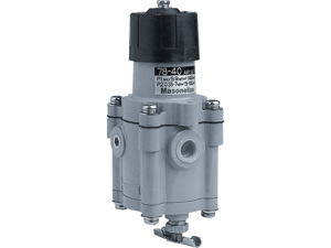
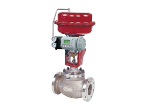
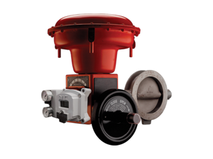
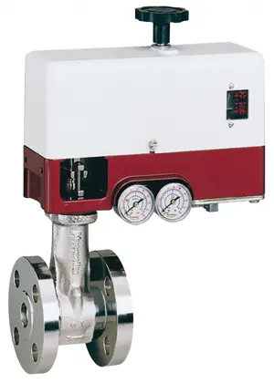
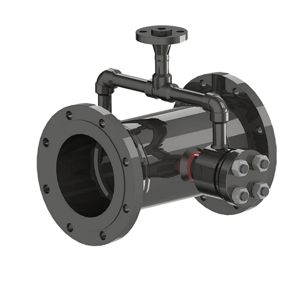
Baker Hughes High Performance Butterfly Valve 39004 Series
Need answers fast?
Explore the manual using AI.
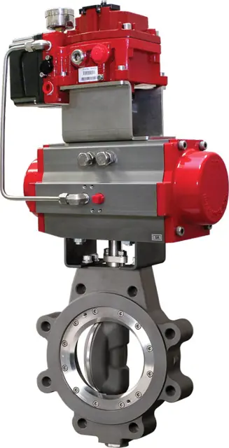
The Baker Hughes High Performance Butterfly Valve 39004 Series is engineered for superior flow control in various industrial applications. This robust valve design ensures reliability and efficiency, making it an ideal choice for demanding environments. Optimize your operations with this high-quality asset from Baker Hughes.
Turn manuals into instant answers
with your AI-powered assistantTurn manuals into instant answers
with your AI-powered assistant
Manual for Baker Hughes High Performance Butterfly Valve 39004 Series
Complete asset maintenance, one click away
Get instant access to all the maintenance information you need. Empower technicians to perform preventive maintenance with asset packages, ready to use right out of the box.

Documents & Manuals
Find all the essential guides in one place.
 Tensioning Guide
- Belt-diagram
- C-120 pulleys
+ 13 more

Work Order Templates
Pre-built workflows to keep your asset running smoothly.
- Daily Electrical System Inspection
- Replace Roller and Pulley
- Install Engine B-120
+ 29 more

Procedures
Integrate maintenance plans directly into your work orders.
- Motion Industries
- Applied Industrial Technologies
- Electrical Brothers
+ 5 more

Parts
Access the parts list for your equipment in MaintainX.
- Drive Motor
- B2 Rollers
- Tensioning System
+ 40 more
Baker Hughes High Performance Butterfly Valve 39004 Series
Create an account to install this asset package.
Maintenance Plans for Baker Hughes High Performance Butterfly Valve Model 39004 Series
Integrate maintenance plans directly into your work orders in MaintainX.
Disc and Stem Replacement
Refer to drawing on page 5 for parts identification.
Note: Stem and disc are supplied as a matched set with taper pins and are to be replaced as a set.
1. For handle-operated valves, loosen set screw (28) and remove handle assembly (27). Remove socket head cap screws (21) and lock washers (22). Remove mounting bracket (20). For actuated valves, unbolt mounting bracket from body and lift actuator assembly off stem.
Note assembly positions before removal.
2. Remove gland retainer nuts (14) and lock washers (13). Remove gland retainer (11), anti-blowout retaining ring or split ring (10) (depending on valve size), and gland ring (7).
3. Hook out stem seals (8) taking care not to scratch stem or stuffing box bore.
4. Remove locating plug (19) and gasket (18).
5. Remove cap screws (17), seat retainer (16), and seat (15).
6. Turn disc to the full open position and drill out tack welds on large end of taper pins (4). Take care to support valve so that disc surfaces are not scratched. Drill sizes to remove tack welds as given in Table 3.

Field Adjustments
Stem Seal Leakage
- Should leakage occur at the stem seals, it may be stopped by retightening the gland retainer nuts to the values specified in Tables 2 or 4. Do not overtighten gland nuts, as this may cause increased operating torque, and improper valve operation or closure. If the leakage cannot be stopped by this action, the stem seals require replacement.
Adjusting Valve Closure
Valves with gear actuators or electric / pneumatic actuators may require adjustment of the travel stops in the actuator to properly close valve for tight shut-off. The following procedure should be followed to set travel or limit stops. (It is recommended that the valve must be removed from line for this procedure and actuator mounting).
1. Using a straight-edge and vernier or depth caliper, measure the distances from the face of the seat retainer to the disc (valve closed) face at the 3 o’clock and 9 o’clock positions (stem is at 12 o’clock position). The measurements must agree within 1/16” (0.062”).
2. If they do not agree, disc must be rotated in the direction of the larger dimension. If the 3 o’clock dimension is larger, the disc is not fully closed, and must be rotated in the “close” direction more. If 9 o’clock dimension is larger, disc is over-closed, and must be opened slightly.
3. The valve disc is at the full open position when the disc is perpendicular to the body. Set the “open” actuator stop for this position. Do not allow the valve to over-open as this may damage the disc seating surfaces by hitting body or attached piping.
4. On gear operators, loosen and adjust the closing stop screw to permit proper disc positioning. Adjust and lock down when disc closure is within measured tolerance in paragraph 1. Open and close valve; recheck measurements before reinstalling in line.
5. For other power actuators, consult the manufacturer’s instructions for setting travel stops, as these vary with actuator model and type.
Seat Replacement
1. With the disc in the closed position, remove the valve from the line.
2. Lay the valve down with the disc in the closed position and the seat retainer side facing up.
3. Remove the socket head cap screws (17), the seat retainer (16), and seat (15).
4. Carefully clean the seat area in the body and seat retainer. Remove foreign matter, dirt, etc. Check disc seating area for nicks or scratches.
5. Place the new seat (15) on disc (2), carefully centering it in the recess in the body.
6. Align the holes in the seat retainer (16) with matching holes in body and carefully place in position on top of seat (15). Be careful not to shift retainer to align holes so that seat is not shifted from correct position. Lightly grease cap screw (17) threads and tighten down evenly, alternating from top to bottom and side-to-side. Tighten to the torque value in Table 2.
7. Operate valve several times and examine seat for any damage before reinstalling the valve in the line.;
Stem Seal Replacement
1. If required, remove handle assembly. Remove socket head cap screws (21) and lock washers (22). Remove mounting bracket (20). For actuated valves, unbolt mounting bracket from body and lift actuator assembly off stem. Note assembly positions before removal.
2. Remove gland retainer nuts (14) and lock washers (13). Remove gland retainer (11) anti-blowout retaining ring or split ring (10) (depending on size), and gland ring (7).
3. Hook out stem seals (8), taking care not to scratch stem or stuffing box bore. Do not remove thrust washer (9), unless further valve disassembly is required.
4. Examine stuffing box bore and stem, clean as necessary to remove any corrosion or foreign matter before installing new seals.
5. Install new seals in stuffing box one at a time, TFE (white) seals first, with the carbon fiber ring at the top. Stagger seal ring joints 180° apart when installing. Tamp each ring to bottom before installing next ring.
Note: On the larger valves it will be necessary to compress each seal before adding the next.
6. Slide gland ring (7) over stem on top of seals (8). Install anti-blowout retaining ring or split ring (10) (depending on valve size). Slide gland retainer (11) over stem and onto gland studs (12). Place lockwashers (13) and hex nuts (14) on studs (12) and tighten finger tight. Tighten gland nuts (14) evenly and alternately to the proper torque value given in Table 2.
7. Remount actuator, or mounting bracket (20) with lock washers (22) and cap screws (21) and handle (27). Tighten handle set screw (28) to secure the handle to the valve stem.
8. Operate valve open and closed several times, to check for binding and to set the stem seals. Loosen gland nuts (14) and retighten to torque value given in Table 2.;
Parts for Baker Hughes High Performance Butterfly Valve 39004 Series
Access the parts list for your equipment in MaintainX.
Lock Washer
-
Stem
-
Hex Nut
-
Handle Assembly
-
Locating Plug
-
Lock Washer
-
Stem
-
Hex Nut
-
Handle Assembly
-
Locating Plug
-
Lock Washer
-
Stem
-
Hex Nut
-
Handle Assembly
-
Locating Plug
-
Unlock efficiency
with MaintainX CoPilot
MaintainX CoPilot is your expert colleague, on call 24/7, helping your team find the answers they need to keep equipment running.
Reduce Unplanned Downtime
Ensure your team follows consistent procedures to minimize equipment failures and costly delays.
Maximize Asset Availability
Keep your assets running longer and more reliably, with standardized maintenance workflows from OEM manuals.
Lower Maintenance Costs
Turn any technician into an expert to streamline operations, maintain more assets, and reduce overall costs.
Thousands of companies manage their assets with MaintainX

'%3e%3cpath%20fill='url(%23b)'%20d='M66.008%2080.068c-5.084-.786-9.763-3.834-12.442-8.68a16.942%2016.942%200%200%201-1.87-5.18c1.096.19%202.203.476%203.298.87%206.525%202.333%2010.836%207.68%2011.014%2012.99ZM51.47%2061.576c.488-5.524%203.62-10.716%208.847-13.597a17.132%2017.132%200%200%201%2011.335-1.882c-.798%208.145-7.43%2014.848-16.038%2015.599-1.417.119-2.799.07-4.144-.12Zm28.564-11.478a17.513%2017.513%200%200%201%203.727%204.62c4.608%208.335%201.584%2018.813-6.75%2023.409a16.988%2016.988%200%200%201-4.359%201.679%2019.624%2019.624%200%200%201-3.977-12.776c.346-7.561%204.942-13.931%2011.36-16.932Z'/%3e%3cpath%20fill='%23110F0D'%20fill-rule='evenodd'%20d='M142.831%2048.324h4.977V77.03h-4.977V48.324Zm27.278%2013.002c.322%201.048.453%202.263.453%203.62v12.073h-4.787V66.208c0-.75-.047-1.572-.154-2.143-.453-2.382-1.822-3.572-4.215-3.572-2.31%200-3.882%201.274-4.43%203.476-.143.596-.226%201.405-.226%202.25v10.8h-4.787V56.623h4.477v2.989c1.536-2.5%203.906-3.43%206.371-3.43%203.488%200%206.263%201.68%207.298%205.144Zm24.636%207.323c0%203.882-2.358%206.525-5.763%207.727-1.298.453-2.632.643-4.62.643h-10.169V48.324h9.085c1.691%200%203.156.143%204.049.38%203.465.93%205.727%203.68%205.727%207.335%200%202.441-.81%204.156-2.762%205.644%202.905%201.417%204.453%203.727%204.453%206.966Zm-15.634-8.656h4.584c1.024%200%201.917-.143%202.536-.417%201.215-.548%201.905-1.608%201.905-3.167%200-1.548-.643-2.572-1.845-3.132-.691-.31-1.762-.452-2.763-.452h-4.417v7.168Zm10.716%208.465c0-1.536-.893-3.37-3.227-3.893-.428-.095-1.036-.143-1.571-.143h-5.918v8.085h5.501c.56%200%201.429-.048%201.953-.167%201.94-.453%203.262-1.846%203.262-3.882Zm47.747-11.847-8.097%2020.408h-4.429l-8.109-20.408h5.191l5.192%2014.574%205.108-14.574h5.144Zm-20.218%2010.002c0%20.69-.036%201.262-.155%201.94h-15.943c.631%202.87%202.714%204.728%205.882%204.728%202.131%200%203.607-.882%204.703-2.525h4.87c-1.762%204.144-5.204%206.692-9.657%206.692-6.084%200-10.537-4.858-10.537-10.49%200-6.108%204.524-10.776%2010.335-10.776%206.239%200%2010.442%204.954%2010.502%2010.43Zm-4.763-1.405c-.333-2.846-2.643-4.858-5.691-4.858-2.894%200-5.287%201.929-5.621%204.858h11.312Zm-72.667%203.44c0%204.787-3.287%208.371-9.419%208.371H119.363V64.66c-1.917.274-3.87.69-5.811%201.238l4.537%2011.121h-5.418l-3.596-9.585c-5.144%202.084-10.085%205.216-14.217%209.585h-4.786L101.8%2048.312h4.56l5.68%2013.883a44.112%2044.112%200%200%201%207.323-1.774V48.312h9.084c1.703%200%203.156.143%204.061.393%203.453.929%205.727%203.667%205.727%207.323%200%201.917-.738%204.179-2.81%205.691%203.06%201.56%204.501%204.025%204.501%206.93Zm-15.634-8.667a62.664%2062.664%200%200%201%202.06-.036c1.703.012%203.239.131%204.608.37%201.441-.549%202.357-1.727%202.357-3.537%200-1.941-.881-3.144-2.488-3.667-.548-.18-1.358-.286-2.322-.286h-4.215v7.156Zm-16.55%203.905-3.715-9.894-6.394%2016.502c2.833-2.595%206.263-4.858%2010.109-6.608Zm27.254%204.74c0-2.775-3.131-4.347-8.513-4.418-.715%200-1.441.011-2.191.047v8.252h5.918c2.548%200%204.786-1.37%204.786-3.882Z'%20clip-rule='evenodd'/%3e%3c/g%3e%3cdefs%3e%3clinearGradient%20id='b'%20x1='51.47'%20x2='85.916'%20y1='62.946'%20y2='62.946'%20gradientUnits='userSpaceOnUse'%3e%3cstop%20stop-color='%23CD9F28'/%3e%3cstop%20offset='1'%20stop-color='%23ECD80B'/%3e%3c/linearGradient%3e%3cclipPath%20id='a'%3e%3cpath%20fill='%23fff'%20d='M51.47%2045.728h186.104V80.14H51.47z'/%3e%3c/clipPath%3e%3c/defs%3e%3c/svg%3e)


More from Baker Hughes


Explore Other Assets


© 2026 MaintainX. All rights reserved.