


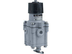
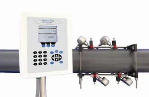
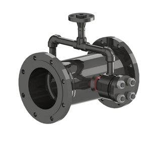
Baker Hughes Gas Clamp-On Ultrasonic Flowmeter GC868
Need answers fast?
Explore the manual using AI.
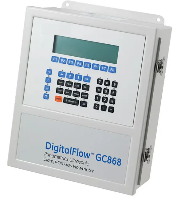
The Baker Hughes Gas Clamp-On Ultrasonic Flowmeter GC868 is a high-precision measurement device designed for non-intrusive flow measurement in various industrial applications. This advanced flowmeter offers reliable performance and easy installation, making it an ideal choice for optimizing flow monitoring and management.
Turn manuals into instant answers
with your AI-powered assistantTurn manuals into instant answers
with your AI-powered assistant
Manual for Baker Hughes Gas Clamp-On Ultrasonic Flowmeter GC868
Complete asset maintenance, one click away
Get instant access to all the maintenance information you need. Empower technicians to perform preventive maintenance with asset packages, ready to use right out of the box.

Documents & Manuals
Find all the essential guides in one place.
 Tensioning Guide
- Belt-diagram
- C-120 pulleys
+ 13 more

Work Order Templates
Pre-built workflows to keep your asset running smoothly.
- Daily Electrical System Inspection
- Replace Roller and Pulley
- Install Engine B-120
+ 29 more

Procedures
Integrate maintenance plans directly into your work orders.
- Motion Industries
- Applied Industrial Technologies
- Electrical Brothers
+ 5 more

Parts
Access the parts list for your equipment in MaintainX.
- Drive Motor
- B2 Rollers
- Tensioning System
+ 40 more
Baker Hughes Gas Clamp-On Ultrasonic Flowmeter GC868
Create an account to install this asset package.
Maintenance Plans for Baker Hughes Gas Clamp-On Ultrasonic Flowmeter Model GC868
Integrate maintenance plans directly into your work orders in MaintainX.
Fuse Replacement
If it has been determined that the fuse in the Model GC868 requires replacement, complete the following steps: 1. Remove the main power to the electronics console.
2. Open the cover on the electronics console. For LVD compliant units, remove the two mounting screws and lift the clear plastic shroud out of the electronics console.
3. Locate the black plastic fuse holder that is mounted on the printed circuit board between the power terminal block (TB1) and the RS232 terminal block. As shown in Figure 4-1 on page 4-8, the fuse holder extends below the main aluminum shroud, and the fuse holder cap is located on the bottom of the fuse holder.
4. Using a small standard screwdriver, turn the fuse holder cap counterclockwise about 1/4 turn. The fuse holder cap, with the captive fuse, will be ejected from the fuse holder.
5. Replace the defective fuse with a new one of the same rating and type. Use only 1-1/4” x 1/4” Slo-Blo fuses, having a rating as indicated in Table 4-1 below and on the wiring diagram label.
6. Press the new fuse into the fuse holder cap and insert the fuse into the fuse holder. While applying a slight pressure with the screwdriver, twist the fuse holder cap 1/4 turn clockwise.
7. For LVD compliant units, place the clear plastic shroud over the standoffs in the electronics console and secure it in place with its two mounting screws. Close the cover on the electronics console.
The Model GC868 flowmeter may now be placed back into service. Reconnect the main power and resume taking measurements.;

LCD Display Replacement
The Model GC868’s measurements are displayed on a a two-pane LCD graphic display panel. The LCD display normally provides years of dependable service, but it is easily field-replaceable when necessary. To replace the LCD display, see Figure 4-1 on page 4-8 for the component locations, and complete the following steps: 1. Remove the printed circuit board, as described in a previous section of this chapter.
2. Using a 3/16” nut driver, remove the four nut/washer sets that secure the display shroud to the inside of the console cover. Lift the display shroud off its mounting studs.
3. Using a 1/4” nut driver, remove the four standoffs that secure the LCD display assembly to the console cover. Lift the LCD display assembly off its mounting studs.
4. Place the new LCD display assembly over the mounting studs on the console cover and fasten it in place with the four standoffs. Make sure that the LCD display assembly is oriented as shown in Figure 4-2 on page 4-9.
5. Position the LCD display cables between the two right side mounting studs, and install the display shroud over the mounting studs. The top and bottom edges of the shroud are bent at a 90° angle to the main surface, and these edges must face inwards toward the display assembly.
6. Fasten the display shroud to the console cover with the four sets of nuts/washers.
Option Card Replacement
The Model GC868 flowmeter can accommodate up to six option cards. The option cards are installed into sockets on the bottom of the printed circuit board, and they are held in place with a metal bracket. A single metal bracket is used to secure all the installed option cards. To install an option card, refer to Figure 4-2 on page 4-9 and complete the following steps: 1. Remove the printed circuit board, as described in a previous section of this chapter.
2. If one or more option cards are already installed, remove the four fasteners that secure the metal bracket to the printed circuit board. Lift the metal bracket straight up and away from the printed circuit board.
3. There are six 32-pin option card sockets (J41–J46) on the rear of the printed circuit board. To install an option card, insert its 32-pin connector into any available option card socket and gently press the card into place. Make sure that the pins in the connector are straight and properly aligned with the socket and that the connector is positioned on the right side of the option card.
4. Repeat step 3 to install any additional option cards.
5. Place the metal bracket over the option cards, making sure that all option cards are aligned with the plastic card guides in the bracket. Secure the metal bracket to the printed circuit board with the snap rivets provided. See Figure 4-1 on page 4-8 for the installed assembly.
Complete the option card installation by proceeding to the Installing the Printed Circuit Board section on page 4-5 of this chapter.;
EPROM Replacement
The Model GC868’s User Program is stored on an erasable programmable read only memory (EPROM) chip. The EPROM, designated as component U4, is located in the top left corner of the bottom of the printed circuit board. See Figure 4-2 on page 4-9 for a rear view of the printed circuit board. EPROM replacement may be required to replace a defective chip or to upgrade to a newer software version
To replace the EPROM, complete the following steps: 1. Remove the printed circuit board, as described in a previous section of this chapter.
2. Place the printed circuit board face down on a clean, flat surface. Locate the EPROM socket at the top left corner of the board.
3. Using a chip puller, remove the EPROM from its socket. If a chip puller is unavailable, a straightened paper clip may be used in the notches at the upper right and lower left corners of the socket. Gently pry the EPROM up, a little at a time, at each notch until it comes free.
4. Make sure that the beveled corner on the new EPROM is aligned with the beveled corner of the socket and place the EPROM into the socket.
5. By applying equal pressure on all four corners, gently press the EPROM into the socket until it is fully seated. Do not strike the EPROM or apply excessive force during this procedure.;
Parts for Baker Hughes Gas Clamp-On Ultrasonic Flowmeter GC868
Access the parts list for your equipment in MaintainX.
Option Card
703-1127-02
Option Card
703-1326-02
Option Card
703-1358
Conduit Plate
421-700
Card Guide
417-027
Option Card
703-1127-02
Option Card
703-1326-02
Option Card
703-1358
Conduit Plate
421-700
Card Guide
417-027
Option Card
703-1127-02
Option Card
703-1326-02
Option Card
703-1358
Conduit Plate
421-700
Card Guide
417-027
Unlock efficiency
with MaintainX CoPilot
MaintainX CoPilot is your expert colleague, on call 24/7, helping your team find the answers they need to keep equipment running.
Reduce Unplanned Downtime
Ensure your team follows consistent procedures to minimize equipment failures and costly delays.
Maximize Asset Availability
Keep your assets running longer and more reliably, with standardized maintenance workflows from OEM manuals.
Lower Maintenance Costs
Turn any technician into an expert to streamline operations, maintain more assets, and reduce overall costs.
Thousands of companies manage their assets with MaintainX

'%3e%3cpath%20fill='url(%23b)'%20d='M66.008%2080.068c-5.084-.786-9.763-3.834-12.442-8.68a16.942%2016.942%200%200%201-1.87-5.18c1.096.19%202.203.476%203.298.87%206.525%202.333%2010.836%207.68%2011.014%2012.99ZM51.47%2061.576c.488-5.524%203.62-10.716%208.847-13.597a17.132%2017.132%200%200%201%2011.335-1.882c-.798%208.145-7.43%2014.848-16.038%2015.599-1.417.119-2.799.07-4.144-.12Zm28.564-11.478a17.513%2017.513%200%200%201%203.727%204.62c4.608%208.335%201.584%2018.813-6.75%2023.409a16.988%2016.988%200%200%201-4.359%201.679%2019.624%2019.624%200%200%201-3.977-12.776c.346-7.561%204.942-13.931%2011.36-16.932Z'/%3e%3cpath%20fill='%23110F0D'%20fill-rule='evenodd'%20d='M142.831%2048.324h4.977V77.03h-4.977V48.324Zm27.278%2013.002c.322%201.048.453%202.263.453%203.62v12.073h-4.787V66.208c0-.75-.047-1.572-.154-2.143-.453-2.382-1.822-3.572-4.215-3.572-2.31%200-3.882%201.274-4.43%203.476-.143.596-.226%201.405-.226%202.25v10.8h-4.787V56.623h4.477v2.989c1.536-2.5%203.906-3.43%206.371-3.43%203.488%200%206.263%201.68%207.298%205.144Zm24.636%207.323c0%203.882-2.358%206.525-5.763%207.727-1.298.453-2.632.643-4.62.643h-10.169V48.324h9.085c1.691%200%203.156.143%204.049.38%203.465.93%205.727%203.68%205.727%207.335%200%202.441-.81%204.156-2.762%205.644%202.905%201.417%204.453%203.727%204.453%206.966Zm-15.634-8.656h4.584c1.024%200%201.917-.143%202.536-.417%201.215-.548%201.905-1.608%201.905-3.167%200-1.548-.643-2.572-1.845-3.132-.691-.31-1.762-.452-2.763-.452h-4.417v7.168Zm10.716%208.465c0-1.536-.893-3.37-3.227-3.893-.428-.095-1.036-.143-1.571-.143h-5.918v8.085h5.501c.56%200%201.429-.048%201.953-.167%201.94-.453%203.262-1.846%203.262-3.882Zm47.747-11.847-8.097%2020.408h-4.429l-8.109-20.408h5.191l5.192%2014.574%205.108-14.574h5.144Zm-20.218%2010.002c0%20.69-.036%201.262-.155%201.94h-15.943c.631%202.87%202.714%204.728%205.882%204.728%202.131%200%203.607-.882%204.703-2.525h4.87c-1.762%204.144-5.204%206.692-9.657%206.692-6.084%200-10.537-4.858-10.537-10.49%200-6.108%204.524-10.776%2010.335-10.776%206.239%200%2010.442%204.954%2010.502%2010.43Zm-4.763-1.405c-.333-2.846-2.643-4.858-5.691-4.858-2.894%200-5.287%201.929-5.621%204.858h11.312Zm-72.667%203.44c0%204.787-3.287%208.371-9.419%208.371H119.363V64.66c-1.917.274-3.87.69-5.811%201.238l4.537%2011.121h-5.418l-3.596-9.585c-5.144%202.084-10.085%205.216-14.217%209.585h-4.786L101.8%2048.312h4.56l5.68%2013.883a44.112%2044.112%200%200%201%207.323-1.774V48.312h9.084c1.703%200%203.156.143%204.061.393%203.453.929%205.727%203.667%205.727%207.323%200%201.917-.738%204.179-2.81%205.691%203.06%201.56%204.501%204.025%204.501%206.93Zm-15.634-8.667a62.664%2062.664%200%200%201%202.06-.036c1.703.012%203.239.131%204.608.37%201.441-.549%202.357-1.727%202.357-3.537%200-1.941-.881-3.144-2.488-3.667-.548-.18-1.358-.286-2.322-.286h-4.215v7.156Zm-16.55%203.905-3.715-9.894-6.394%2016.502c2.833-2.595%206.263-4.858%2010.109-6.608Zm27.254%204.74c0-2.775-3.131-4.347-8.513-4.418-.715%200-1.441.011-2.191.047v8.252h5.918c2.548%200%204.786-1.37%204.786-3.882Z'%20clip-rule='evenodd'/%3e%3c/g%3e%3cdefs%3e%3clinearGradient%20id='b'%20x1='51.47'%20x2='85.916'%20y1='62.946'%20y2='62.946'%20gradientUnits='userSpaceOnUse'%3e%3cstop%20stop-color='%23CD9F28'/%3e%3cstop%20offset='1'%20stop-color='%23ECD80B'/%3e%3c/linearGradient%3e%3cclipPath%20id='a'%3e%3cpath%20fill='%23fff'%20d='M51.47%2045.728h186.104V80.14H51.47z'/%3e%3c/clipPath%3e%3c/defs%3e%3c/svg%3e)


More from Baker Hughes


Explore Other Assets


© 2026 MaintainX. All rights reserved.