


Baker Hughes Energy Management Control Valve 49000 Series
Need answers fast?
Explore the manual using AI.
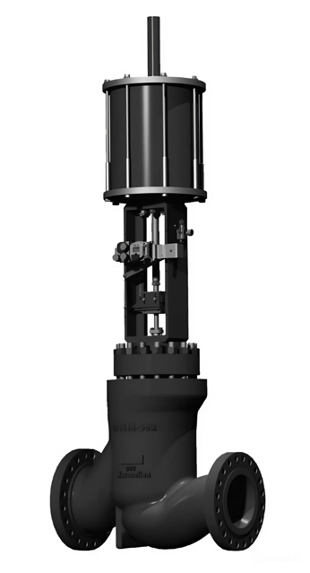
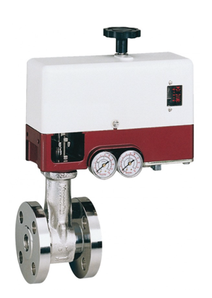
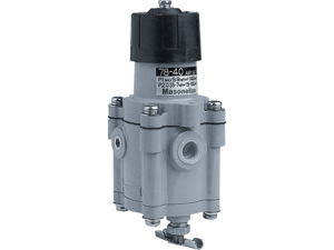
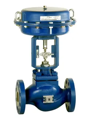
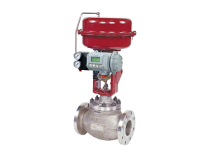
The Baker Hughes Energy Management Control Valve 49000 Series is designed for precision flow control in industrial applications. This robust valve ensures optimal performance and reliability, making it essential for energy management systems. Regular maintenance and the right spare parts are crucial for its longevity and efficiency.
Turn manuals into instant answers
with your AI-powered assistantTurn manuals into instant answers
with your AI-powered assistant
Manual for Baker Hughes Energy Management Control Valve 49000 Series
Complete asset maintenance, one click away
Get instant access to all the maintenance information you need. Empower technicians to perform preventive maintenance with asset packages, ready to use right out of the box.

Documents & Manuals
Find all the essential guides in one place.
 Tensioning Guide
- Belt-diagram
- C-120 pulleys
+ 13 more

Work Order Templates
Pre-built workflows to keep your asset running smoothly.
- Daily Electrical System Inspection
- Replace Roller and Pulley
- Install Engine B-120
+ 29 more

Procedures
Integrate maintenance plans directly into your work orders.
- Motion Industries
- Applied Industrial Technologies
- Electrical Brothers
+ 5 more

Parts
Access the parts list for your equipment in MaintainX.
- Drive Motor
- B2 Rollers
- Tensioning System
+ 40 more
Baker Hughes Energy Management Control Valve 49000 Series
Create an account to install this asset package.
Maintenance Plans for Baker Hughes Energy Management Control Valve Model 49000 Series
Integrate maintenance plans directly into your work orders in MaintainX.
Seating Surfaces Maintenance
The seat ring seating surface and valve plug seating surface must be completely free of dents, wear, or scratches. Consult factory should you see any signs of slight deterioration prior to attempting touchup. If a slight defect exists on either the seat ring seating surface or the valve plug seating surface, lapping can be applied per the following instructions: - Clean body gasket surface areas.
- Install a new seat ring gasket (10B). Note: Seat ring gasket (10B) is temporarily placed to hold the seat ring during lapping.
- It is imperative to use a new gasket or a test part having the same geometrical characteristics in order to ensure the correct position of the seat ring during lapping.
- Place seat ring (5) or seat ring diffuser (Not Shown) in the body, noting the seating angle is up.
- Spread a fine layer of high quality lapping compound (600 grit) on the seating surface.
- Assemble the cage (4) and (if applicable) cage retainer (Not Shown) and the plug assembly (Items 6, 8 & 9) into the valve body (1) per the valve plug assembly instructions.
- Assemble the bonnet (2) and the guide bushing (7).
- Place an appropriate tool on the valve stem (8) thread to allow for manual rotation.
- Lap by slightly rotating the valve plug in alternate directions.

Valve with Graphite Packing Maintenance
To replace Graphite packing, it is necessary to separate the valve plug stem from the actuator stem.
- Remove the packing flange nuts (19) from the packing flange studs (18).
- Lift the packing flange (17) and packing follower (16) up along the valve stem (8).
- By means of a puller, remove the packing (15) being careful not to damage the sealing surface of the packing box or the valve plug stem.
- Replace the packing (15). Press a back-up ring (carbon/graphite/Inconel braided ring) into the bonnet (2). Next press the expanded graphite rings into the packing area one at a time. Press an additional back-up ring into the packing area.
- Reassemble the packing follower (16) and the packing flange (17).
- Tighten the packing flange nuts (19) without over compressing the packing rings.
- Open and close the valve several times then retighten the packing as required.
- Put the valve back into service and check for leakage.
Packing Box Maintenance
- Tight sealing within the packing box is obtained by compression of the packing (15). Compression must be achieved by evenly tightening the packing flange nuts (19) on the packing flange (17). Periodic re-tightening of the packing flange nuts may be required to maintain proper sealing.
- Be careful not to over tighten the packing as this could prevent proper operation of the valve. If leakage persists after maximum packing compression, then the packing needs to be changed.;
Metal Seal Maintenance
For the two-piece bonnet configurations: - Prior to reassembly, the metal seal (11) should be inspected for cracks or signs of wear.
- The metal seal can be reused if it is free from scratches, erosion, corrosion, or any other type of damage.
- If slight wear exists on the metal seal, a new layer of coating should be re-applied to the original condition by the factory or a Masoneilan Authorized Repair Center.
- Prior to reassembly of the valve, inspect the inside of the valve body around the area where the metal seal seats. It is common to find slight ridges or depressions from where the seal was originally seated.
- To prevent this potential leakage, machine the seating angle of the bonnet at 40 degrees by approximately 0.1 inches (2.5 mm) deep, thus causing the metal seal to seat further down inside the valve body (on a new un-deformed surface). Refer to Figure 4 for details.
- If this procedure is required more than twice, please consult the factory.;
Seal Rings Maintenance
- Seal rings (14), back-up rings (22), retaining ring (Not Shown), and conical springs (Not Shown) can be reused if they are free of scratches, erosion, corrosion, or other damage.;
Parts for Baker Hughes Energy Management Control Valve 49000 Series
Access the parts list for your equipment in MaintainX.
Hexagon nut
-
Separator plate Model 52/53
-
Stud
720017027
Stud
720015679
Stud
11487935
Hexagon nut
-
Separator plate Model 52/53
-
Stud
720017027
Stud
720015679
Stud
11487935
Hexagon nut
-
Separator plate Model 52/53
-
Stud
720017027
Stud
720015679
Stud
11487935
Unlock efficiency
with MaintainX CoPilot
MaintainX CoPilot is your expert colleague, on call 24/7, helping your team find the answers they need to keep equipment running.
Reduce Unplanned Downtime
Ensure your team follows consistent procedures to minimize equipment failures and costly delays.
Maximize Asset Availability
Keep your assets running longer and more reliably, with standardized maintenance workflows from OEM manuals.
Lower Maintenance Costs
Turn any technician into an expert to streamline operations, maintain more assets, and reduce overall costs.
Thousands of companies manage their assets with MaintainX

'%3e%3cpath%20fill='url(%23b)'%20d='M66.008%2080.068c-5.084-.786-9.763-3.834-12.442-8.68a16.942%2016.942%200%200%201-1.87-5.18c1.096.19%202.203.476%203.298.87%206.525%202.333%2010.836%207.68%2011.014%2012.99ZM51.47%2061.576c.488-5.524%203.62-10.716%208.847-13.597a17.132%2017.132%200%200%201%2011.335-1.882c-.798%208.145-7.43%2014.848-16.038%2015.599-1.417.119-2.799.07-4.144-.12Zm28.564-11.478a17.513%2017.513%200%200%201%203.727%204.62c4.608%208.335%201.584%2018.813-6.75%2023.409a16.988%2016.988%200%200%201-4.359%201.679%2019.624%2019.624%200%200%201-3.977-12.776c.346-7.561%204.942-13.931%2011.36-16.932Z'/%3e%3cpath%20fill='%23110F0D'%20fill-rule='evenodd'%20d='M142.831%2048.324h4.977V77.03h-4.977V48.324Zm27.278%2013.002c.322%201.048.453%202.263.453%203.62v12.073h-4.787V66.208c0-.75-.047-1.572-.154-2.143-.453-2.382-1.822-3.572-4.215-3.572-2.31%200-3.882%201.274-4.43%203.476-.143.596-.226%201.405-.226%202.25v10.8h-4.787V56.623h4.477v2.989c1.536-2.5%203.906-3.43%206.371-3.43%203.488%200%206.263%201.68%207.298%205.144Zm24.636%207.323c0%203.882-2.358%206.525-5.763%207.727-1.298.453-2.632.643-4.62.643h-10.169V48.324h9.085c1.691%200%203.156.143%204.049.38%203.465.93%205.727%203.68%205.727%207.335%200%202.441-.81%204.156-2.762%205.644%202.905%201.417%204.453%203.727%204.453%206.966Zm-15.634-8.656h4.584c1.024%200%201.917-.143%202.536-.417%201.215-.548%201.905-1.608%201.905-3.167%200-1.548-.643-2.572-1.845-3.132-.691-.31-1.762-.452-2.763-.452h-4.417v7.168Zm10.716%208.465c0-1.536-.893-3.37-3.227-3.893-.428-.095-1.036-.143-1.571-.143h-5.918v8.085h5.501c.56%200%201.429-.048%201.953-.167%201.94-.453%203.262-1.846%203.262-3.882Zm47.747-11.847-8.097%2020.408h-4.429l-8.109-20.408h5.191l5.192%2014.574%205.108-14.574h5.144Zm-20.218%2010.002c0%20.69-.036%201.262-.155%201.94h-15.943c.631%202.87%202.714%204.728%205.882%204.728%202.131%200%203.607-.882%204.703-2.525h4.87c-1.762%204.144-5.204%206.692-9.657%206.692-6.084%200-10.537-4.858-10.537-10.49%200-6.108%204.524-10.776%2010.335-10.776%206.239%200%2010.442%204.954%2010.502%2010.43Zm-4.763-1.405c-.333-2.846-2.643-4.858-5.691-4.858-2.894%200-5.287%201.929-5.621%204.858h11.312Zm-72.667%203.44c0%204.787-3.287%208.371-9.419%208.371H119.363V64.66c-1.917.274-3.87.69-5.811%201.238l4.537%2011.121h-5.418l-3.596-9.585c-5.144%202.084-10.085%205.216-14.217%209.585h-4.786L101.8%2048.312h4.56l5.68%2013.883a44.112%2044.112%200%200%201%207.323-1.774V48.312h9.084c1.703%200%203.156.143%204.061.393%203.453.929%205.727%203.667%205.727%207.323%200%201.917-.738%204.179-2.81%205.691%203.06%201.56%204.501%204.025%204.501%206.93Zm-15.634-8.667a62.664%2062.664%200%200%201%202.06-.036c1.703.012%203.239.131%204.608.37%201.441-.549%202.357-1.727%202.357-3.537%200-1.941-.881-3.144-2.488-3.667-.548-.18-1.358-.286-2.322-.286h-4.215v7.156Zm-16.55%203.905-3.715-9.894-6.394%2016.502c2.833-2.595%206.263-4.858%2010.109-6.608Zm27.254%204.74c0-2.775-3.131-4.347-8.513-4.418-.715%200-1.441.011-2.191.047v8.252h5.918c2.548%200%204.786-1.37%204.786-3.882Z'%20clip-rule='evenodd'/%3e%3c/g%3e%3cdefs%3e%3clinearGradient%20id='b'%20x1='51.47'%20x2='85.916'%20y1='62.946'%20y2='62.946'%20gradientUnits='userSpaceOnUse'%3e%3cstop%20stop-color='%23CD9F28'/%3e%3cstop%20offset='1'%20stop-color='%23ECD80B'/%3e%3c/linearGradient%3e%3cclipPath%20id='a'%3e%3cpath%20fill='%23fff'%20d='M51.47%2045.728h186.104V80.14H51.47z'/%3e%3c/clipPath%3e%3c/defs%3e%3c/svg%3e)


More from Baker Hughes


Explore Other Assets


© 2026 MaintainX. All rights reserved.