


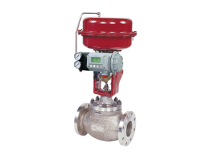
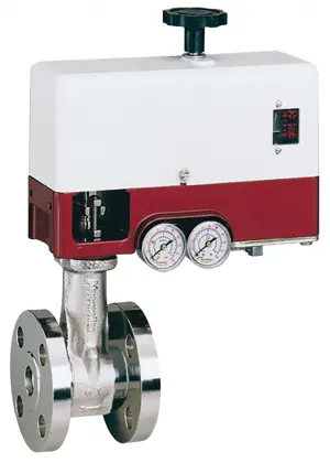
Baker Hughes ElectromaticTM Ball Valve System 3500-1/2/3 EBV Series
Need answers fast?
Explore the manual using AI.
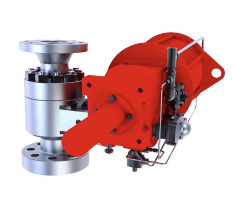
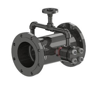
The Baker Hughes Electromatic™ Ball Valve System 3500-1/2/3 EBV Series is a reliable and efficient solution for controlling fluid flow in industrial applications. This advanced valve system offers precise operation and durability, making it ideal for demanding environments. Ensure optimal performance with regular maintenance and quality spare parts.
Turn manuals into instant answers
with your AI-powered assistantTurn manuals into instant answers
with your AI-powered assistant
Manual for Baker Hughes ElectromaticTM Ball Valve System 3500-1/2/3 EBV Series
Complete asset maintenance, one click away
Get instant access to all the maintenance information you need. Empower technicians to perform preventive maintenance with asset packages, ready to use right out of the box.

Documents & Manuals
Find all the essential guides in one place.
 Tensioning Guide
- Belt-diagram
- C-120 pulleys
+ 13 more

Work Order Templates
Pre-built workflows to keep your asset running smoothly.
- Daily Electrical System Inspection
- Replace Roller and Pulley
- Install Engine B-120
+ 29 more

Procedures
Integrate maintenance plans directly into your work orders.
- Motion Industries
- Applied Industrial Technologies
- Electrical Brothers
+ 5 more

Parts
Access the parts list for your equipment in MaintainX.
- Drive Motor
- B2 Rollers
- Tensioning System
+ 40 more
Baker Hughes ElectromaticTM Ball Valve System 3500-1/2/3 EBV Series
Create an account to install this asset package.
Maintenance Plans for Baker Hughes ElectromaticTM Ball Valve System Model 3500-1/2/3 EBV Series
Integrate maintenance plans directly into your work orders in MaintainX.
Ball Valve Inspection
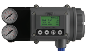
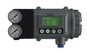
To inspect for proper wiring of the controller, control station and the actuator, refer to Figure 14 and 15.
If trouble is encountered in the controller, the control station or the actuator, refer to the Trouble Shooting Chart shown in Table 5.; Each block in the chart identifies a particular piece of equipment (i.e., the controller, the control station, the actuator assembly, etc.), and the terminal to check when the system is malfunctioning.
Therefore, when numbers and letters, such as T7 or T8, are encountered in the Trouble Shooting Chart, these refer to specific terminals, such as 7 or 8, in a particular piece of equipment.;

Ball Valve Maintenance
A. Seat Leakage If leakage should occur use the following procedure to determine and correct the cause:
1. Verify that the normally closed solenoid valve is energized and vented. To accomplish this, check the voltage across terminal 2 and 3 in the actuator junction box. There should be voltage at these terminals when the valve is closed. If no voltage is present, check continuity across terminals 3 and 4.
There should be continuity across these terminals when the valve is closed. If there is no continuity, adjust the closed side actuator switch lever cam until the circuit is closed. Actuate the valve and check for leakage.
2. If the switch is properly adjusted and leakage continues, the ball and seat assembly must be removed and checked. The valve must be isolated from system pressure before it can be disassembled.
Using the procedures outlined in the disassembly section of this manual remove the adapter flange, ball, and seat assembly. Inspect the spherical radius in the seat for cutting or flaking of the chrome carbide. Inspect the spherical radius of the ball for cutting or flaking of the chrome carbide.
Very light flaking at the edge of the bore is acceptable. If the seat is damaged and the ball has galling or flaking of the carbide coating the entire ball and seat and loader assembly must be replaced. Remove the old gasket and clean the gasket surfaces of the body and the busing. Reassemble the valve using the procedures outlined in the assembly section of this manual. Pressurize and actuate the valve. Check for leakage.
3. If a new ball, seat and loader assembly has been installed and the valve still leaks, the stem bearing pad must be replaced. Refer to the disassembly and assembly section of this manual for disassembly and assembly instruction. The valve must be isolated from system pressure when removing and replacing the stem bearing pad. New packing must be installed each time the stem is removed.
B. Packing Leakage
Should packing leakage occur, tighten the two packing nuts in the quarter turn increments. Check after each quarter turn adjustment to see if leakage has stopped. The packing should be tightened only enough to stop the leakage. If the leakage can not be stopped by tightening the gland nuts, the valve should be repacked with new packing.
Ball Valve Cleaning
The 3500 Series EBV Valve parts may normally be cleaned with wire brushes, and low pressure air.
Whatever method is used, clean the parts safely and use care to prevent damage to the environment.
If internal parts are cleaned with industrial solvents or cleaning solutions, take precautions to protect yourself from potential danger of breathing fumes, chemical burns, or explosion.
See the manufacturer’s Safety Data Sheet for safe handling instructions and information about protective clothing and equipment for use when working with the chemical.; The outside surfaces of the actuator, Type 2537 control station, and Type 3539 controller box may be cleaned by wiping with a damp cloth.;
Parts for Baker Hughes ElectromaticTM Ball Valve System 3500-1/2/3 EBV Series
Access the parts list for your equipment in MaintainX.
Ball
4B
Ball and Seat Assembly
4
Discharge Collar
3
Solenoid (Closed)
25C
Drain
24
Ball
4B
Ball and Seat Assembly
4
Discharge Collar
3
Solenoid (Closed)
25C
Drain
24
Ball
4B
Ball and Seat Assembly
4
Discharge Collar
3
Solenoid (Closed)
25C
Drain
24
Unlock efficiency
with MaintainX CoPilot
MaintainX CoPilot is your expert colleague, on call 24/7, helping your team find the answers they need to keep equipment running.
Reduce Unplanned Downtime
Ensure your team follows consistent procedures to minimize equipment failures and costly delays.
Maximize Asset Availability
Keep your assets running longer and more reliably, with standardized maintenance workflows from OEM manuals.
Lower Maintenance Costs
Turn any technician into an expert to streamline operations, maintain more assets, and reduce overall costs.
Thousands of companies manage their assets with MaintainX

'%3e%3cpath%20fill='url(%23b)'%20d='M66.008%2080.068c-5.084-.786-9.763-3.834-12.442-8.68a16.942%2016.942%200%200%201-1.87-5.18c1.096.19%202.203.476%203.298.87%206.525%202.333%2010.836%207.68%2011.014%2012.99ZM51.47%2061.576c.488-5.524%203.62-10.716%208.847-13.597a17.132%2017.132%200%200%201%2011.335-1.882c-.798%208.145-7.43%2014.848-16.038%2015.599-1.417.119-2.799.07-4.144-.12Zm28.564-11.478a17.513%2017.513%200%200%201%203.727%204.62c4.608%208.335%201.584%2018.813-6.75%2023.409a16.988%2016.988%200%200%201-4.359%201.679%2019.624%2019.624%200%200%201-3.977-12.776c.346-7.561%204.942-13.931%2011.36-16.932Z'/%3e%3cpath%20fill='%23110F0D'%20fill-rule='evenodd'%20d='M142.831%2048.324h4.977V77.03h-4.977V48.324Zm27.278%2013.002c.322%201.048.453%202.263.453%203.62v12.073h-4.787V66.208c0-.75-.047-1.572-.154-2.143-.453-2.382-1.822-3.572-4.215-3.572-2.31%200-3.882%201.274-4.43%203.476-.143.596-.226%201.405-.226%202.25v10.8h-4.787V56.623h4.477v2.989c1.536-2.5%203.906-3.43%206.371-3.43%203.488%200%206.263%201.68%207.298%205.144Zm24.636%207.323c0%203.882-2.358%206.525-5.763%207.727-1.298.453-2.632.643-4.62.643h-10.169V48.324h9.085c1.691%200%203.156.143%204.049.38%203.465.93%205.727%203.68%205.727%207.335%200%202.441-.81%204.156-2.762%205.644%202.905%201.417%204.453%203.727%204.453%206.966Zm-15.634-8.656h4.584c1.024%200%201.917-.143%202.536-.417%201.215-.548%201.905-1.608%201.905-3.167%200-1.548-.643-2.572-1.845-3.132-.691-.31-1.762-.452-2.763-.452h-4.417v7.168Zm10.716%208.465c0-1.536-.893-3.37-3.227-3.893-.428-.095-1.036-.143-1.571-.143h-5.918v8.085h5.501c.56%200%201.429-.048%201.953-.167%201.94-.453%203.262-1.846%203.262-3.882Zm47.747-11.847-8.097%2020.408h-4.429l-8.109-20.408h5.191l5.192%2014.574%205.108-14.574h5.144Zm-20.218%2010.002c0%20.69-.036%201.262-.155%201.94h-15.943c.631%202.87%202.714%204.728%205.882%204.728%202.131%200%203.607-.882%204.703-2.525h4.87c-1.762%204.144-5.204%206.692-9.657%206.692-6.084%200-10.537-4.858-10.537-10.49%200-6.108%204.524-10.776%2010.335-10.776%206.239%200%2010.442%204.954%2010.502%2010.43Zm-4.763-1.405c-.333-2.846-2.643-4.858-5.691-4.858-2.894%200-5.287%201.929-5.621%204.858h11.312Zm-72.667%203.44c0%204.787-3.287%208.371-9.419%208.371H119.363V64.66c-1.917.274-3.87.69-5.811%201.238l4.537%2011.121h-5.418l-3.596-9.585c-5.144%202.084-10.085%205.216-14.217%209.585h-4.786L101.8%2048.312h4.56l5.68%2013.883a44.112%2044.112%200%200%201%207.323-1.774V48.312h9.084c1.703%200%203.156.143%204.061.393%203.453.929%205.727%203.667%205.727%207.323%200%201.917-.738%204.179-2.81%205.691%203.06%201.56%204.501%204.025%204.501%206.93Zm-15.634-8.667a62.664%2062.664%200%200%201%202.06-.036c1.703.012%203.239.131%204.608.37%201.441-.549%202.357-1.727%202.357-3.537%200-1.941-.881-3.144-2.488-3.667-.548-.18-1.358-.286-2.322-.286h-4.215v7.156Zm-16.55%203.905-3.715-9.894-6.394%2016.502c2.833-2.595%206.263-4.858%2010.109-6.608Zm27.254%204.74c0-2.775-3.131-4.347-8.513-4.418-.715%200-1.441.011-2.191.047v8.252h5.918c2.548%200%204.786-1.37%204.786-3.882Z'%20clip-rule='evenodd'/%3e%3c/g%3e%3cdefs%3e%3clinearGradient%20id='b'%20x1='51.47'%20x2='85.916'%20y1='62.946'%20y2='62.946'%20gradientUnits='userSpaceOnUse'%3e%3cstop%20stop-color='%23CD9F28'/%3e%3cstop%20offset='1'%20stop-color='%23ECD80B'/%3e%3c/linearGradient%3e%3cclipPath%20id='a'%3e%3cpath%20fill='%23fff'%20d='M51.47%2045.728h186.104V80.14H51.47z'/%3e%3c/clipPath%3e%3c/defs%3e%3c/svg%3e)


More from Baker Hughes


Explore Other Assets


© 2026 MaintainX. All rights reserved.